RF Guru
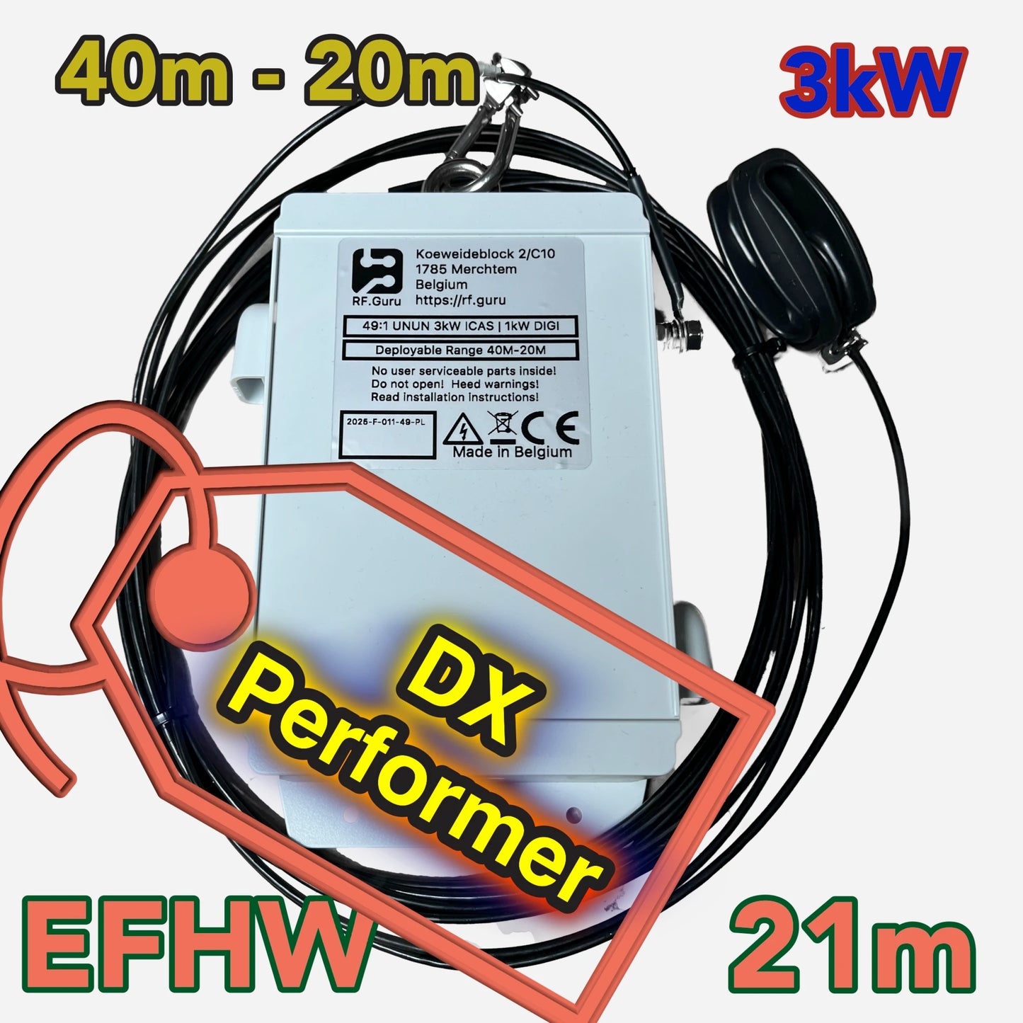
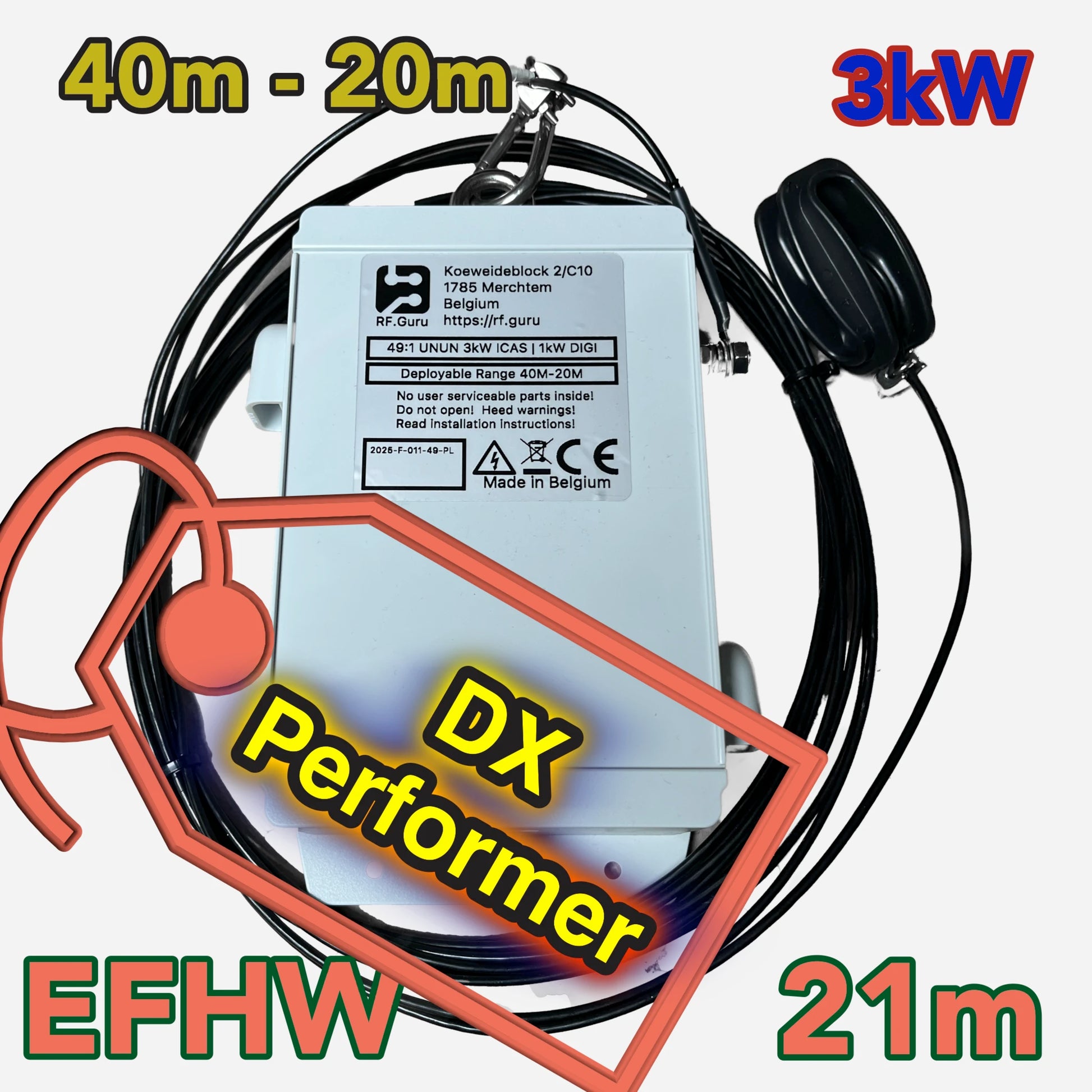
EFHW4020 3kW High Power End-fed Half-wave Dual Band 40M 20M
EFHW4020 3kW High Power End-fed Half-wave Dual Band 40M 20M
Couldn't load pickup availability
2All our products are handmade, and fulfilment times may vary depending on order volume. Please allow 2–3 weeks for your order to be completed and shipped.
The EFHW8040 is a dual-band end-fed half-wave antenna designed for exceptional performance across HF bands, 40m and 20m. This antenna provides reliable, efficient communication for portable, emergency, or permanent installations, ensuring resonance across its frequency range with minimal compromise.
End-Fed antennas deployment tool
Why RF.Guru Pushes Dual-Band EFHW for High-Power (3kW-4kW)
Why Do I Need a Kilowatt-Rated ANTENNA If I Only Run 100 Watts?
Need less power ?
250W Version (Multiband version)
2kW Version (Multiband version)
Common mode choke
For optimal performance, a common mode choke should be installed approximately 2 meters from the feedpoint. Using multiple common mode chokes along the feedline can further reduce common mode noise.
(Read our advice: Optimizing End-Fed Antennas with High-CMR Chokes)
Installation options
This top-band antenna can be configured as an sloper, flattop, or inverted V; however, we recommend the sloper of flattop setup. Ensure the horizontal portion is at least 10 meters above ground, and the feed point is positioned at a minimum height of 10 meter.
Electrical Specifications
-
Power Ratings:
- 3000W ICAS (Intermittent Commercial and Amateur Service)
- 1500W CCS (Continuous Commercial Service)
- 1000W FT8/FT4
- For ICAS and CCS power definitions, More info
-
Frequency Range:
- Covers 40m, 20m.
- Covers 40m, 20m.
- Feedpoint Impedance: Integrated 49:1 UNUN transformer for precise impedance matching to 50-ohm systems.
- Insertion Loss: Less than 0.2 dB, ensuring maximum power transfer.
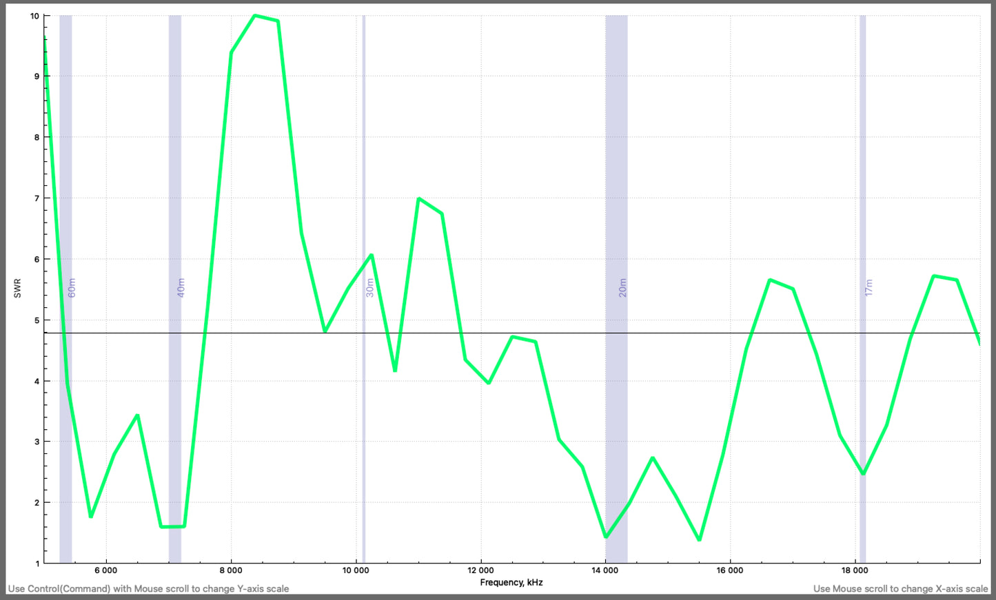
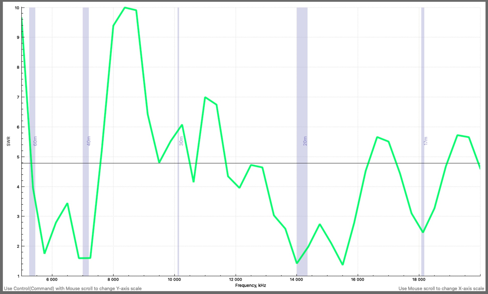
- VSWR: Typically less than 2:1 on supported bands with proper deployment.
Mechanical Characteristics
- Core: High-performance ferrite core optimized for stability and low loss.
- Transformer: Integrated 49:1 impedance transformer with heat-resistant Teflon wire.
- Connector: Professional-grade PL connector, weatherproof to IP66 when sealed.
-
Antenna Wire:
- Premium 41m of hard-drawn, tinned copper wire with a cross-linked polyethylene (XLPE) sheath for exceptional durability and weather resistance.
- Flexible stranded construction ensures ease of deployment and handling.
- Diameter: 2mm, specifically designed for stationary use, providing a robust and long-lasting solution for outdoor installations.
- Enclosure: Rugged polycarbonate housing, waterproof to IP64, UV-resistant, and shockproof.
- Weight: Approx. 650g.
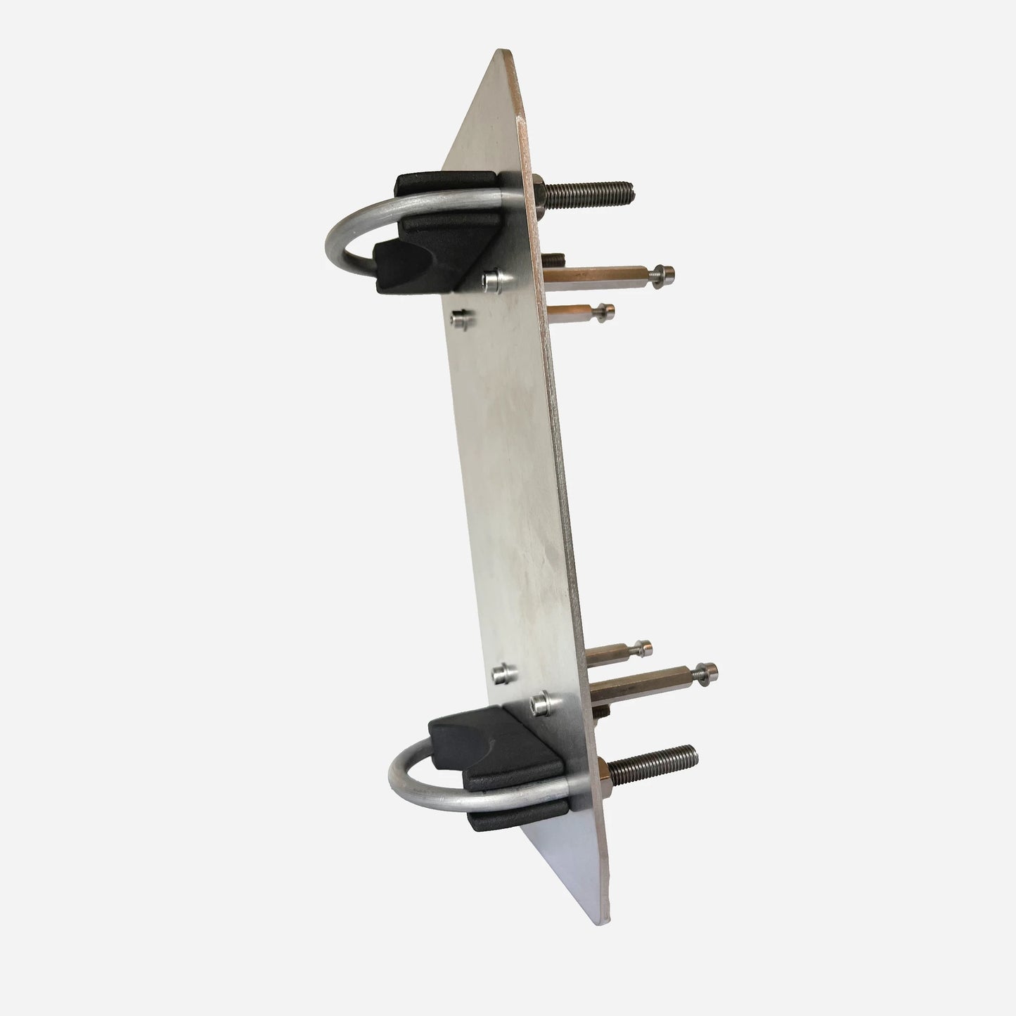
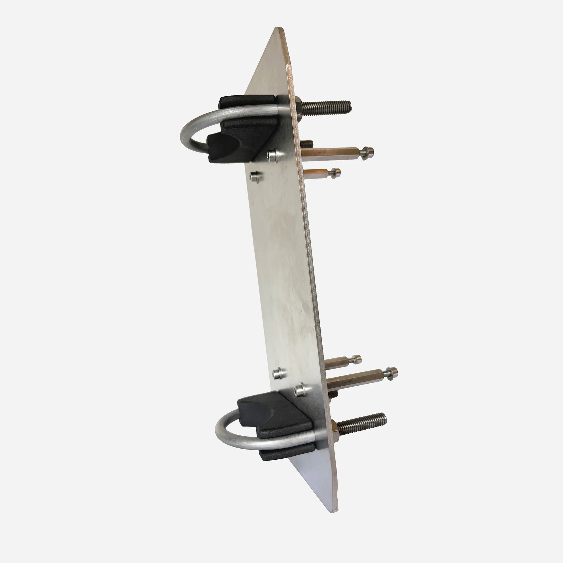
Mounting Kit (Optional)
- 1 x Stainless steel (type 316) mounting plate.
- 2 x Stainless steel U-bolt mast clamps (60/M8).
- 2 x Black nylon tube inlays.
- 8 x Stainless steel hex socket cap screws (DIN 912, M4 x 12mm).
- 4 x Stainless steel spacers (50mm).
Deployable Frequency Range
- Covers 40m and 20m, with resonance on:
-
40m, 20m.
-
40m, 20m.
Power Handling Notes
- For VSWR values < 2.0:1:
- 3000W ICAS
- 1500W CCS
- 1000W FT8/FT4 (high duty cycle modes)
- For VSWR values > 2.0:1, power de-rating is advised:
- < 1000W PeP for VSWR > 3:1
- < 100W PeP for VSWR > 5:1
Key Advantages
- Wide Frequency Coverage: Resonant on 40M and 20M HF bands without traps or coils.
- Ease of Deployment: Easy to install, ideal for field-day and permanent setups.
- Reduced RFI: Integrated common-mode choke eliminates unwanted currents.
- Rugged and Weatherproof: Built to withstand the elements, making it suitable for long-term outdoor use.
- Durable Antenna Wire: Hard-drawn, tinned copper wire with XLPE sheath ensures superior longevity and performance, even in harsh conditions.
Conclusion
The EFHW4020 is the perfect solution for amateur radio enthusiasts seeking a dual-band antenna that delivers performance, durability, and versatility. Whether you're setting up for field-day operations, emergency use, or a permanent station, the EFHW4020 ensures reliable communications with minimal effort.
Disclaimer on SWR and Wire Antennas
At RF.Guru, all our antenna tests, including SWR measurements, are conducted under controlled conditions with the antenna installed at a standard height of 15 meters above ground level in an open environment. These tests are designed to provide a baseline for performance and ensure consistency across our product evaluations.
However, it is important to note that SWR and antenna performance can vary significantly based on several factors, including but not limited to:
- Installation Height: Antennas mounted higher or lower than 10 meters may exhibit different SWR values.
- Surrounding Environment: Proximity to trees, buildings, or other structures can impact performance due to reflections and absorption.
- Ground Conductivity: Soil composition, moisture levels, and terrain can influence radiation patterns and impedance.
- Feedline Length and Quality: Variations in coaxial cable length, quality, or the presence of common-mode currents can affect SWR readings.
- Nearby Metal Objects: Power lines, fences, or other metallic objects can introduce detuning effects.
We recommend that customers perform SWR measurements after installation to fine-tune their setup for optimal performance in their specific environment. If you have any questions or encounter challenges, our team is available to provide guidance and support.
Share
