RF Guru
1kW High Power 1:1 Antenna Tuner Balun
1kW High Power 1:1 Antenna Tuner Balun
Couldn't load pickup availability
All our products are handmade, and fulfilment times may vary depending on order volume. Please allow 2–3 weeks for your order to be completed and shipped.
Correct Use of RF.Guru Antenna Tuner Baluns
Function
Doublets or loops are often deployed on multiple frequency bands using an antenna tuner. Often balanced transmission lines are chosen to feed such antennas, in order to ensure low losses, even under high VSWR conditions. Two wire transmission lines only act truly symmetrically when driven by a perfect balanced source. Most antenna tuners however are a-symmetrical (unbalanced) with respect to ground. Therefore a balanced to unbalanced network is needed to adapt both natures.
This function is perfectly accomplished by a good wideband common-mode choke type BALUN placed at the output of an a-symmetric antenna tuner.
As this BALUN is placed in a random impedance environment, it can be subjected to very high voltages or currents. So the two wire transmission line on such BALUN needs to be designed for high voltage withstand, rather than for a 50 Ohms characteristic impedance.
To accomplish this, the Teflon insulated wires are additionally slipped in Teflon sleeves having a voltage withstand of 24 kV/mm. This ensures that it will not arc over, even when positioned in a voltage node, as a result of e.g. an antenna being half wave resonant at some frequencies.
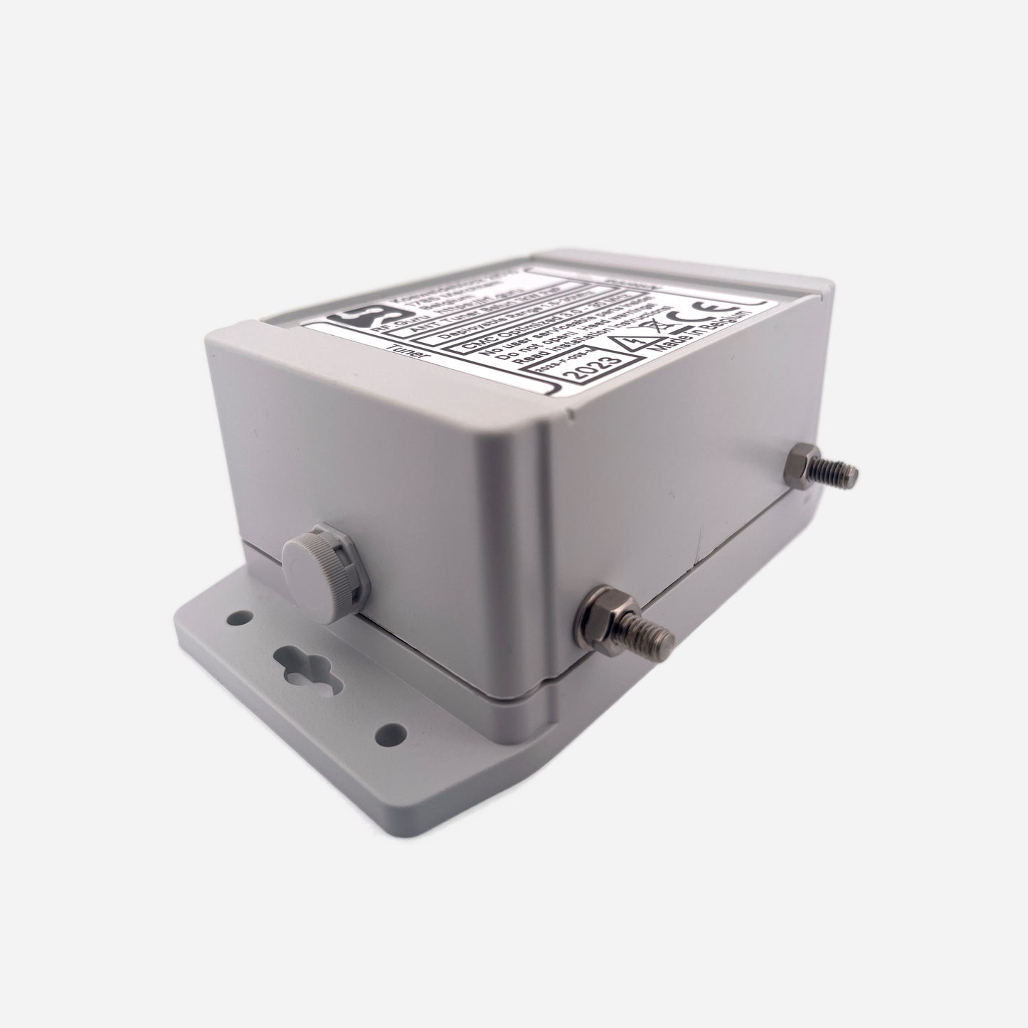
This BALUN is a special variant of the standard 1/1 Common-Mode Choke current BALUN wound with a two wire transmission line instead of a Teflon coaxial cable. It is available with a coaxial input connector, as well as with screw terminals an input and output.
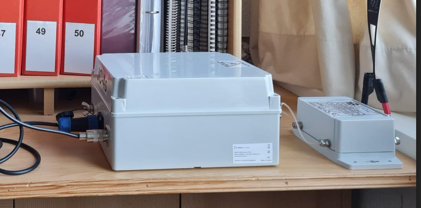
It can be deployed at the output of an a-symmetrical antenna tuner, at the transition between coaxial cable and balanced line in a G5RV configuration or even after a symmetrical antenna tuner to maximize symmetry and block any common-mode current that may be caused due to the inevitable unbalance in any antenna.
Our latest version has wire connection terminals on sides of enclosure, in order to increase creepage distance an thus provide additional insulation for abnormal high voltages (e.g. surges due to lightning).
Mechanical Characteristics
- Optimized 61 mm diameter toroidal ferrites
- Heat resistant teflon wire, inserted in teflon sleeving, providing high breakdown voltage.
- Stainless steel M6 transmission line connection terminals. Stainless steel type 316 More info.
- Waterproof (IP64) and shock proof polycarbonate UV resistant enclosure. More info.
- Weight: +/- 500 g.
Electrical properties
- Conservatively rated 1/1 transmission line transformer.
- Operation principle: Common-Mode Choke.
- Very high common-mode impedance. (Substantially higher than what’s obtainable with the “beads over coax” approach).
- Max. power:
- 1000 W PeP @ VSWR < 2.0/1 (ICAS)
- For ICAS and CCS power definitions, More info
- Deployable frequency range: 1.5 to 30 MHz.
- Low HF variant: optimized for 1,5 – 15 MHz.
- Mid HF variant: optimized for 3 – 30 MHz.
General ANTENNA TUNER BALUN user installation guide & safety instructions
Share