RF Guru
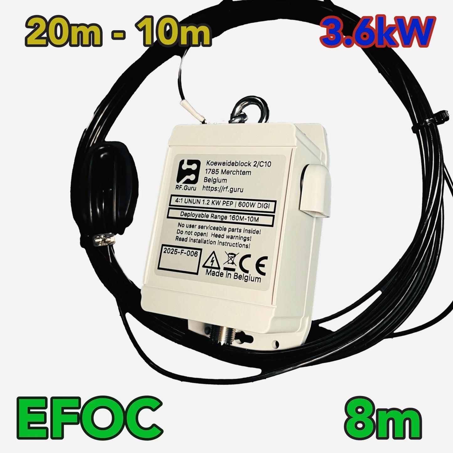
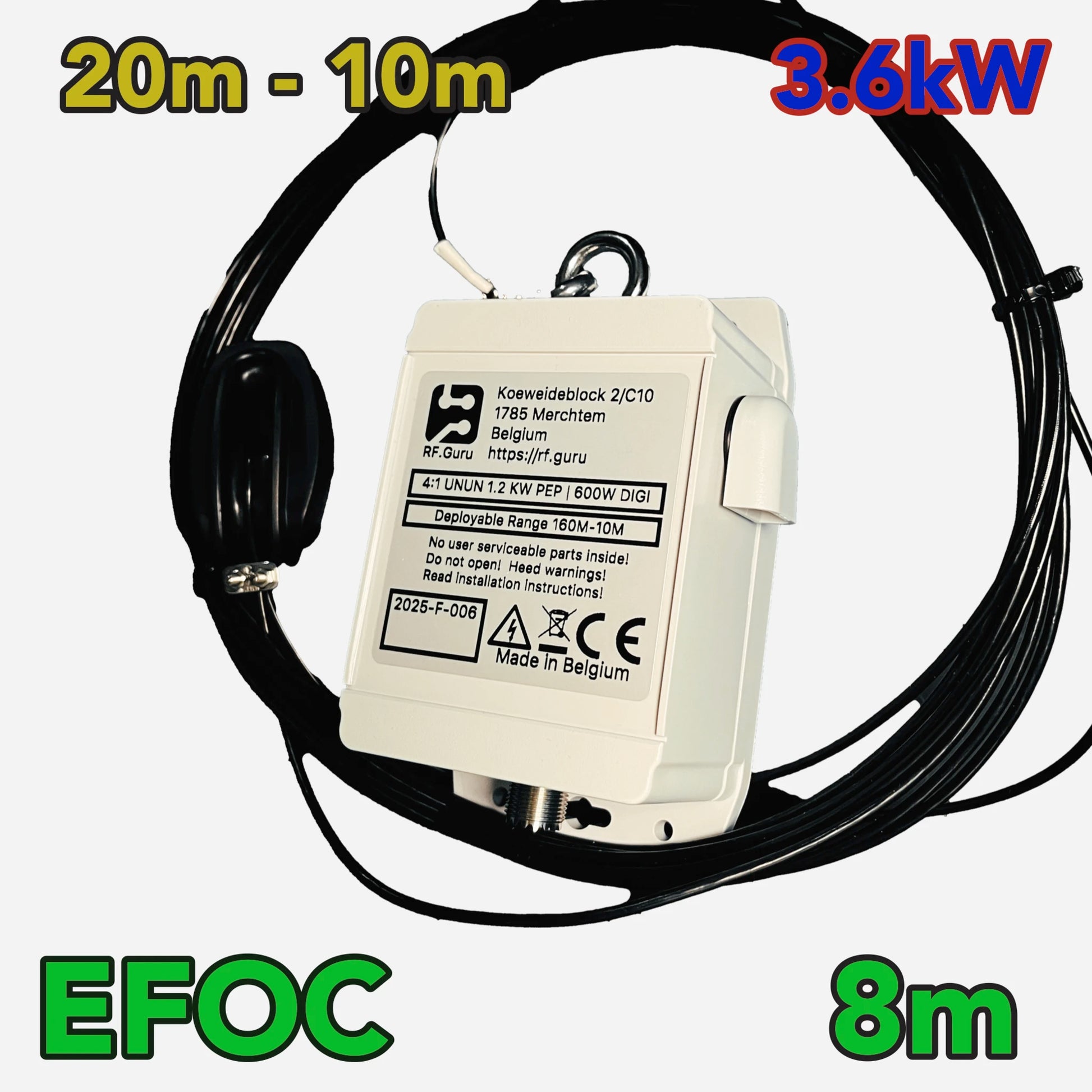
3.6kW End-fed Off-Center EFOC8 20-6M
3.6kW End-fed Off-Center EFOC8 20-6M
Couldn't load pickup availability
EFOC8: A Compact 20–6 m Current System
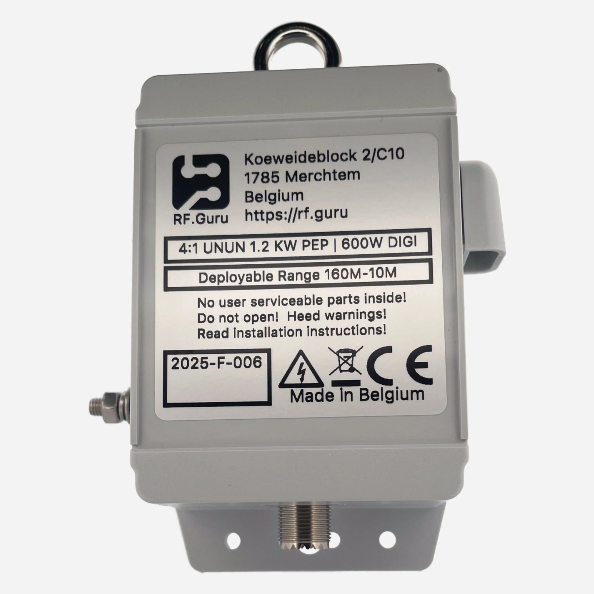
An approximately 7.6 m effective radiator, integrated 4:1 UNUN and selectable coax or wire return path. Extra radiator wire is supplied intentionally so the antenna can be measured and tuned in its installed geometry.
Fulfilment normally takes approximately 2–3 weeks, depending on order volume.
Measure the delivered wire, mark 7.6 m as the electrical starting dimension and leave the surplus folded back during commissioning.
Choose the Return-Path Version
The exterior of the first 2.2 m is the short return section. The supplied ferrite choke belongs at that boundary.
This option uses the dedicated return wire and does not include the coax-counterpoise cable/choke package.
Transformer, radiator, return path, choke and feedline must be evaluated as one installed antenna.
Do not tune the display alone. The antenna should be swept across every intended band with the return section, choke and remaining coax fixed. A low SWR does not prove low loss or controlled exterior current.
Electrical and Mechanical Summary
| Item | Current specification |
|---|---|
| Operating range | 20 m, 17 m, 15 m, 12 m, 10 m and 6 m; tuner need depends on installation |
| Radiator | 7.6 m effective starting dimension; about 8 m or slightly more physical wire supplied for fold-back and strain relief |
| Coax version | Approximately 16 m EXTRAFLEX-BURY-7; supplied choke at approximately 2.2 m |
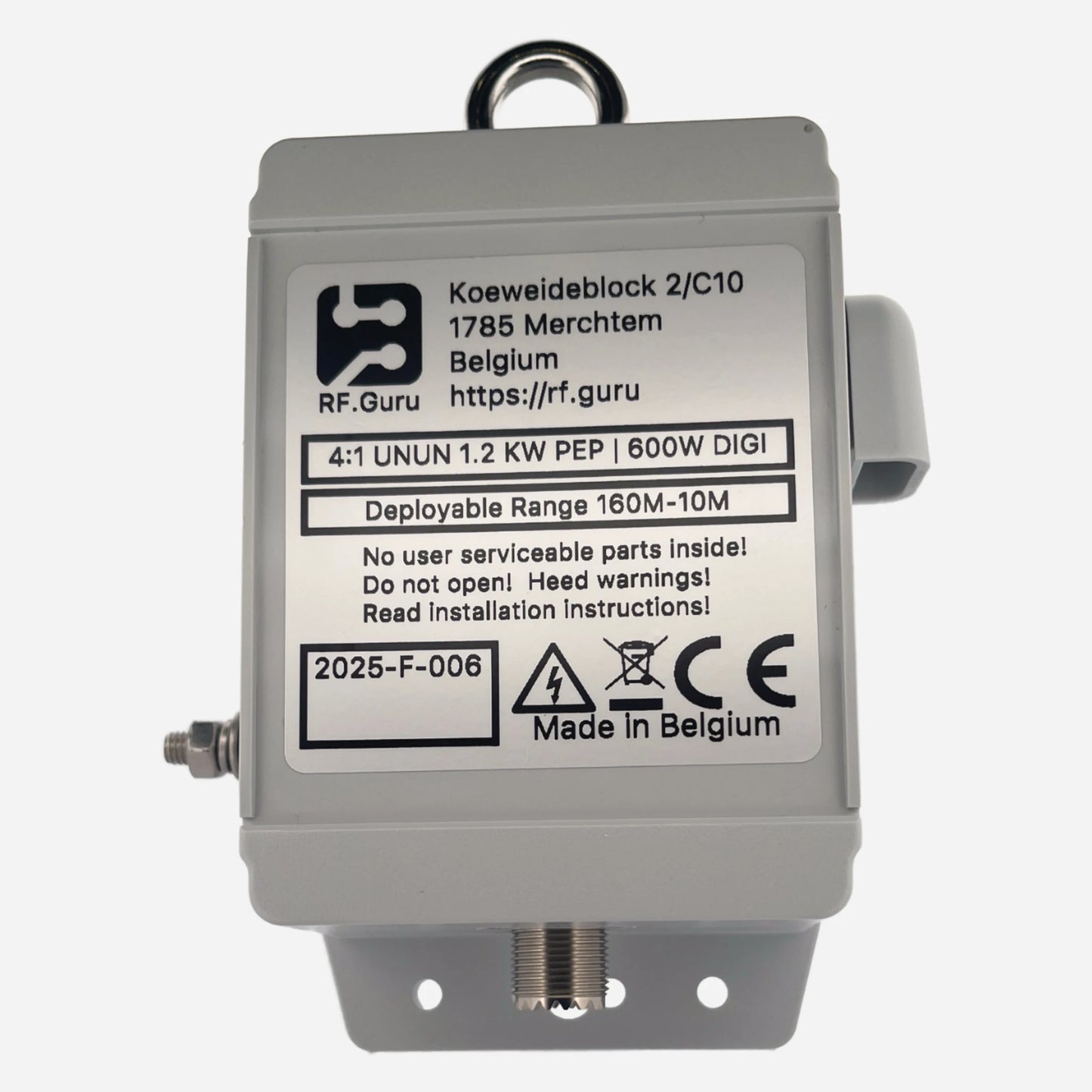
| Transformer | Integrated 4:1 UNUN; published insertion loss below 0.2 dB within the qualified boundary |
| Typical installed VSWR | Below 2.5:1 on supported bands with proper deployment; installation-dependent |
| Connector | SO-239; weatherproof to IP66 when correctly sealed |
| Enclosure | UV- and impact-resistant polycarbonate, rated IP64 |
| Approximate weight | 650 g |
Power Versions
| Version | ICAS | CCS | FT8/FT4 |
|---|---|---|---|
| Single core | 2,400 W PEP at VSWR < 2.0:1 | 1,200 W PEP at VSWR < 2.0:1 | 850 W at VSWR < 1.5:1 |
| Dual core | 3,600 W PEP at VSWR < 2.0:1 | 1,800 W PEP at VSWR < 2.0:1 | 1,250 W at VSWR < 1.5:1 |
The baseline choke is not the transformer rating. The supplied coax-version choke is intended for approximately 200 W SSB or 100 W FT8 in a clean installation. Higher power requires a common-mode solution qualified for the actual current, voltage, frequency, duty and cooling.

Installation Manuals
Wire measurement, 2.2 m return section, choke placement, multiband tuning and safety.
De volledige Nederlandstalige installatie- en afstemprocedure.
Verify the common-mode boundary at the required frequency and power.
Interpret version labels against waveform and duty cycle.
Voltage, current, mismatch, duty cycle and heating belong to the full operating case.
Mini-FAQ
- Is the supplied wire exactly 7.6 m? No. About 8 m or slightly more is intentionally supplied; measure and fold the surplus before cutting.
- Where does the coax-version choke go? At approximately 2.2 m from the feedpoint.
- Does every version include coax? No. The M6 counterpoise-wire version does not include the coax/choke package.
- Will every band have the same SWR at every site? No. Height, surroundings, ground and cable routing affect the installed response.
- Does the transformer rating define the complete antenna limit? No. The weakest component and actual mismatch, duty, current and temperature define it.