Understanding the Null of a Shielded Active H-Field Loop Antenna
Shielded active H-field loop antennas, like the RF.Guru OctaLoop, are popular among HF listeners and ham radio operators because they can be noticeably quieter than many wire antennas in electrically noisy environments. Their directional receive pattern and deep nulls can help reduce man-made interference (QRM), improve weak-signal readability, and assist with direction finding.
A common question is whether a shielded active loop needs to be mounted on a rotor for HF reception, or whether occasional manual re-orientation is enough. The answer depends on what you’re trying to accomplish (general listening vs. aggressive QRM nulling vs. direction finding) and on how the signal is arriving (groundwave vs. skywave/multipath).
The Null in a Vertically Mounted OctaLoop
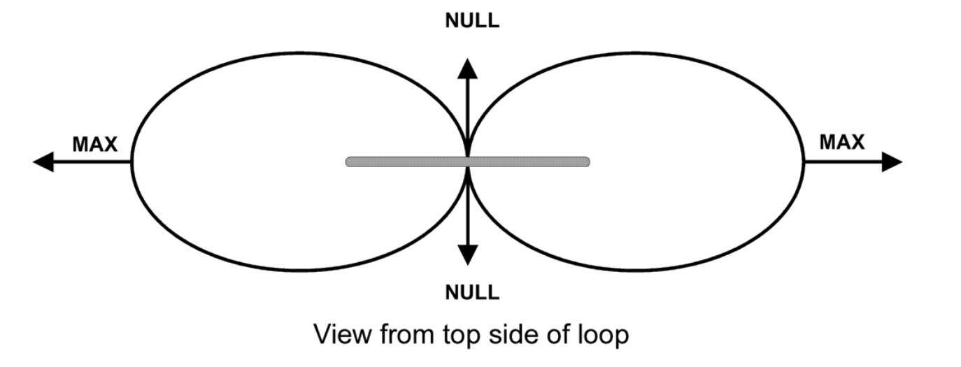
The gray line represents the loop antenna seen from above.
In 3D, the ideal free-space receive pattern of a small magnetic loop is often illustrated like this (a “doughnut” / torus shape around the loop’s axis):

For a small loop (electrically small compared with the wavelength), the deepest nulls occur along the loop’s axis (i.e., perpendicular to the plane of the loop). If you are looking at the loop “face on” (broadside to its plane), you are looking along the direction of the ideal null.
Maximum pickup occurs in directions that lie in the plane of the loop. In the horizontal plane, a vertically mounted loop therefore behaves like a classic figure-eight: two broad maxima and two deep nulls that are 180° apart.
This is why loops are useful for interference reduction and direction finding: rotating the loop until an unwanted signal drops into the null can dramatically reduce it. Keep in mind that a null-based bearing has a natural 180° ambiguity (front/back) unless you add another method to resolve it.
What Determines the Null in a Loop Antenna?
The null in a magnetic receive loop is primarily a geometric/symmetry effect: the loop responds to the time-varying magnetic flux through its area. When the arriving field produces little (or no) magnetic-field component normal to the loop’s plane, the net induced voltage becomes very small, creating the null. In real installations, the null is rarely “infinite” because of imbalance, nearby conductors, feedline coupling, and multipath.
Several practical factors determine when the null applies and how deep it will be:
Loop Orientation and Polarization
- Magnetic-field coupling is the key: a loop responds mainly to the magnetic-field component normal to the loop plane. “Vertical” or “horizontal” polarization describes the electric field, so the best orientation depends on how the accompanying magnetic field is oriented at your location.
- Shielding helps with electric-noise pickup: a well-designed shielded/balanced loop tends to reduce capacitive (E-field) coupling to nearby noise sources, which is often why it sounds quieter in homes full of electronics.
- Real HF signals are often mixed polarization: ionospheric propagation, reflections, and local scattering can rotate or mix polarization, which can partially “fill in” what would be a perfect null in free space.
Arrival Angle and Propagation Mode
- Groundwave / low-angle signals: for signals arriving predominantly from the horizon, the loop’s figure-eight azimuth pattern is usually easy to observe, and the null direction is often repeatable.
- Skywave / multipath signals: HF skywave can arrive from multiple elevation angles and azimuths at once. Even if one path is nulled, other paths may not be, so the null can become shallower or appear to “wander.”
- Nearby interference sources: very local noise sources are often in the near field, where the simple far-field pattern assumptions don’t fully apply. You may find multiple minima, broader nulls, or a null direction that shifts with frequency.
Frequency and “Electrical Size”
- As long as the loop remains electrically small (well below a wavelength in circumference), the classic pattern with deep axis nulls generally holds.
- As the loop becomes a larger fraction of a wavelength (toward the high end of its coverage), pattern symmetry and null depth can change, and the environment (mast, coax, nearby metal) can become more influential.
Installation Details That Can Spoil a Deep Null
- Common-mode current on the feedline can re-radiate or pick up noise and reduce null depth. A good common-mode choke at the antenna end often helps.
- Nearby metal (gutters, railings, fences, masts) can distort the pattern and shift the null direction.
- Amplifier overload from very strong local signals can make nulling appear worse than it should be. Gain management and filtering can help in tough RF environments.
Do You Need a Rotor for HF Reception?
For most HF receiving scenarios, a rotor is optional. If your main goal is to reduce a dominant, fixed noise source (for example, a particular direction where power-line noise or a neighborhood device lives), you can often mount the loop on a fixed mast and simply aim the loop’s null at that noise source.
Manual rotation is often sufficient when the loop is installed where you can easily access it, or when you only need to “trim” the azimuth occasionally. The loop’s null is typically sharp enough that even small changes in orientation can make an audible difference.
A rotor becomes more valuable when:
- You want to do direction finding (DF) in a repeatable way.
- Your interference environment changes throughout the day and you want fast, precise adjustments.
- The antenna is mounted in a location where manual rotation is impractical or unsafe.
Using Two Loops for Flexible Noise Reduction
Another effective strategy is using two loops oriented roughly 90° to each other. This can provide more flexibility, but it’s worth describing accurately:
- Two independent patterns: each loop has its own figure-eight pattern. By switching between the two loops, you can choose the one whose null best suppresses the current noise direction.
- Combining requires a method: you don’t automatically get “deeper nulls” just by having two loops. To synthesize a different pattern (for example, a cardioid-like response or a steerable null), you typically need a phasing/combining network (often with careful amplitude and phase control).
- Practical placement tip: place loops far enough from large metal objects and from each other to reduce mutual coupling, and route feedlines so they don’t become part of the antenna.
Active Magnetic Loop Reception of NVIS Signals on 80m and 40m
An active magnetic receive loop can receive NVIS (Near Vertical Incidence Skywave) signals on 80m and 40m, but its effectiveness depends strongly on orientation, local noise, and how close the arriving skywave is to “straight down.”
Key Point: Where the Loop’s Pattern Has Its Null
- A horizontal small loop (loop plane horizontal, axis vertical) has an ideal null toward zenith. That means it is usually not the best choice if your goal is strong reception of near-vertical arrivals.
- A vertical small loop (loop plane vertical, axis horizontal) can have strong response to higher elevation angles (including many NVIS arrivals), but it remains directional in azimuth, so you may need to rotate it if your desired NVIS station sits in (or near) a null.
Best Orientation for NVIS Reception (Practical Guidance)
- Classic NVIS antenna (best overall): a low horizontal dipole or inverted-V is still the go-to solution for strong, reliable NVIS coverage.
- Receive loop option: if you’re using a magnetic receive loop because it’s quieter in your environment, a vertical mounting is typically the more practical starting point for NVIS than a horizontal mounting.
- Typical NVIS dipole height: about 0.1λ to 0.2λ. For 80m this is roughly 8–17 m; for 40m roughly 4–9 m.
| Antenna Type | NVIS Reception | Notes |
|---|---|---|
| Horizontal dipole / inverted-V (low height) | Excellent | Classic NVIS solution around 0.1λ–0.2λ height |
| Vertical active magnetic receive loop | Good | Often quieter in high-QRM locations; azimuthal nulls may require rotation |
| Horizontal active magnetic receive loop | Fair | Ideal pattern has a zenith null; real-world installations may still hear NVIS but usually not “best case” |
Conclusion
For most HF receiving applications, mounting a shielded active H-field loop like the RF.Guru OctaLoop on a rotor is not strictly necessary. Manual orientation adjustments—or even a fixed mounting aimed to place a deep null on your dominant noise source—can deliver excellent results.
A rotor becomes especially useful for direction finding, rapidly changing noise environments, or installations where you cannot conveniently reposition the loop. If you want even more flexibility, two orthogonal loops (with switching or a proper combining/phasing approach) can provide additional ways to manage QRM and improve reception.
Interested in more technical content like this? Subscribe to our notification list — we only send updates when new articles or blogs are published: https://listmonk.rf.guru/subscription/form
Questions or experiences to share? Feel free to contact RF.Guru or join our feedback group!
Written by Joeri Van Dooren, ON6URE – RF, electronics, and software engineer; complex platform and antenna designer; founder of RF.Guru. Focused on active and passive antennas, RF transformers, and custom RF solutions, with experience in telecom and broadcast hardware and software platforms.