RF.Guru
1–500 MHz 4-Way SMA Splitter / Combiner
1–500 MHz 4-Way SMA Splitter / Combiner
Couldn't load pickup availability
One RF signal. Four connections.
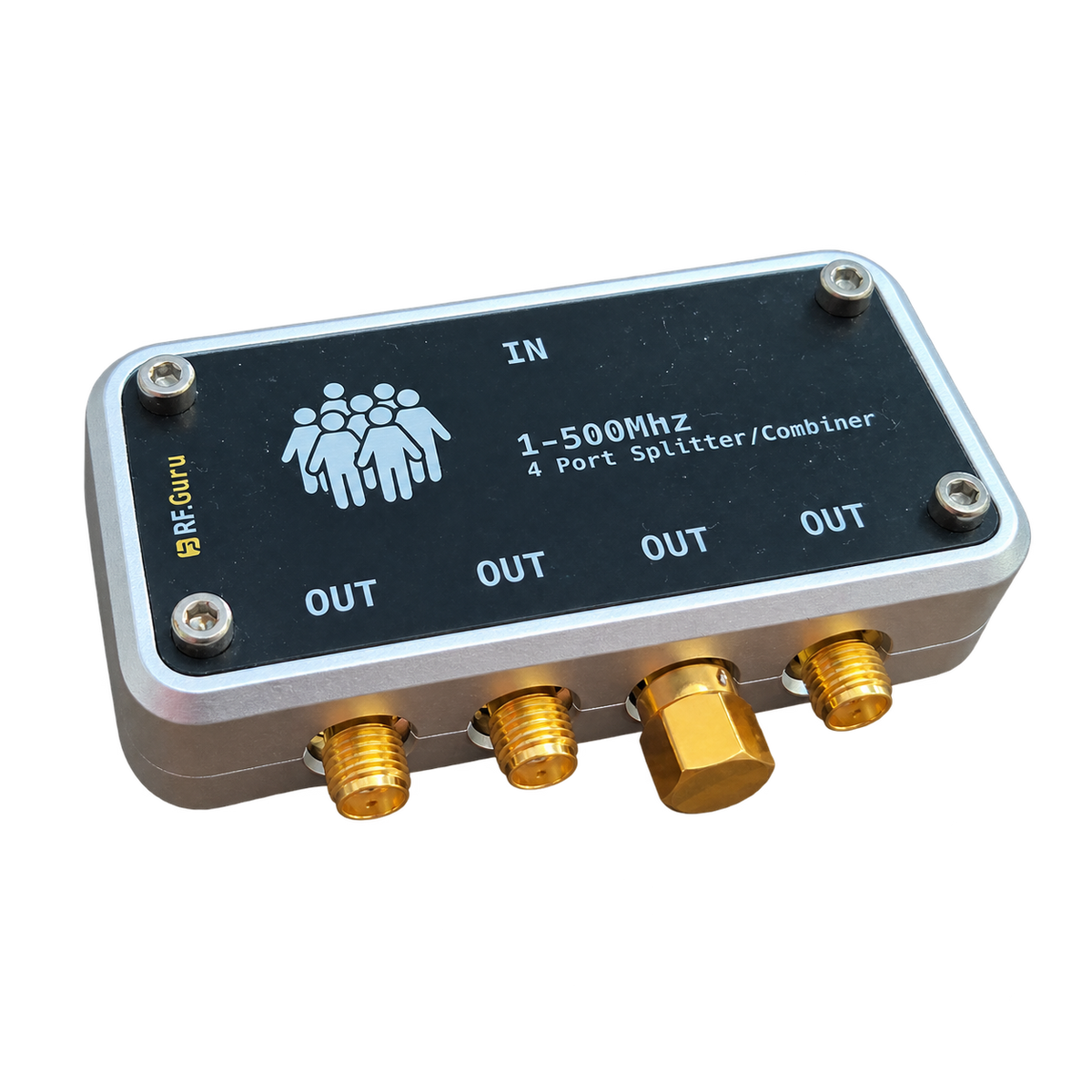
Share a receiving antenna or a low-level test signal between four 50 Ω paths. This compact, enclosed splitter / combiner covers 1–500 MHz and uses Würth SMA connectors, with one common port marked IN and four branch ports marked OUT.
Connect the antenna or signal source to IN and the receivers to OUT. The isolated branches reduce interaction between connected loads compared with simply joining coax cables together.
The passive network also works in reverse for combining signals. Its four paths have nominally equal phase; it does not introduce the 90° phase shift of a quadrature hybrid.
Understand the signal level
Dividing power equally between four outputs gives each branch one quarter of the input power: approximately 6 dB below the input, before additional loss. The excess insertion loss in the table is added to that division loss. For example, a typical 0.5 dB excess loss means approximately 6.5 dB total input-to-output loss.
For reception, allow for this loss when assessing the noise floor and available signal level. The splitter distributes the signal; it does not amplify it.
Connect it correctly
- Use 50 Ω coaxial connections and SMA male plugs to mate with the five SMA female ports.
- Fit a 50 Ω termination to every unused branch to maintain the intended matching and isolation. Using fewer receivers does not turn it into a lower-loss two-way splitter.
- Use an appropriate external power-injection arrangement for an active antenna. DC pass-through and bias-tee operation are not specified for this unit.
RF specifications
| Splitter-core parameter | 1–10 MHz | 10–250 MHz | 250–500 MHz |
|---|---|---|---|
| Excess insertion loss, typical / maximum | 0.4 / 1.2 dB | 0.5 / 1.2 dB | 0.8 / 1.8 dB |
| Output isolation, typical / minimum | 32 / 18 dB | 30 / 20 dB | 25 / 18 dB |
| Amplitude imbalance, maximum | 0.4 dB | 0.5 dB | 0.8 dB |
| Phase imbalance, maximum | 2° | 5° | 7° |
These RF figures are the splitter-core specifications, not measurements of the complete RF.Guru assembly. Connectors, PCB layout and installation contribute to complete-unit performance. Excess insertion loss excludes the nominal 6 dB four-way division loss.
Power limits and combining
This unit is intended for receiving and low-level signal work. The splitter core has an absolute maximum common-port input of 0.5 W (+27 dBm) in splitter operation with matched branch loads, and a separate absolute maximum internal dissipation of 0.25 W. These are component absolute-maximum limits, not recommended operating levels or a qualified transmitter rating for this assembly.
When combining, the relative phase and amplitude of the input signals determine how much power is dissipated internally. Unequal, unrelated or opposing signals can heat the isolation network. The 0.5 W splitter limit is not a 0.5 W rating for each combiner input.
Download the two-page RF.Guru datasheet with the frequency-band specifications, a connection diagram and practical operating notes.
Follow RF.Guru updates
Get new product notes and engineering articles by email.
Join the notification list →Quick answers
- Does it need a power supply? No. This is a passive RF network.
- Can I leave unused outputs open? Fit 50 Ω terminations to unused branches for the intended matching and isolation.
- Does it cover HF? Yes. The specified range is 1–500 MHz, including the amateur HF bands, 6 m, 2 m and 70 cm.
- Can I connect transmitter outputs? This listing is for reception and low-level signal work. It is not a transmitter power combiner.
Share