RF Guru
1.5kW ICAS Dual Core High Power 1:1 Antenna Tuner Current Balun or Choke
1.5kW ICAS Dual Core High Power 1:1 Antenna Tuner Current Balun or Choke
Couldn't load pickup availability
The 1.5 kW ICAS Dual-Core 1:1 Antenna Tuner Balun / Current Choke is designed for balanced open-wire and ladder-line systems using external tuners. It converts an unbalanced tuner output to a balanced line, maintaining true current symmetry and eliminating common-mode RF that can disturb tuner readings or cause RF feedback.
Correct Use of RF.Guru Antenna Tuner Baluns
Baluns in a Nutshell
How Much Choking Do You Really Need — for RX and TX?
Function
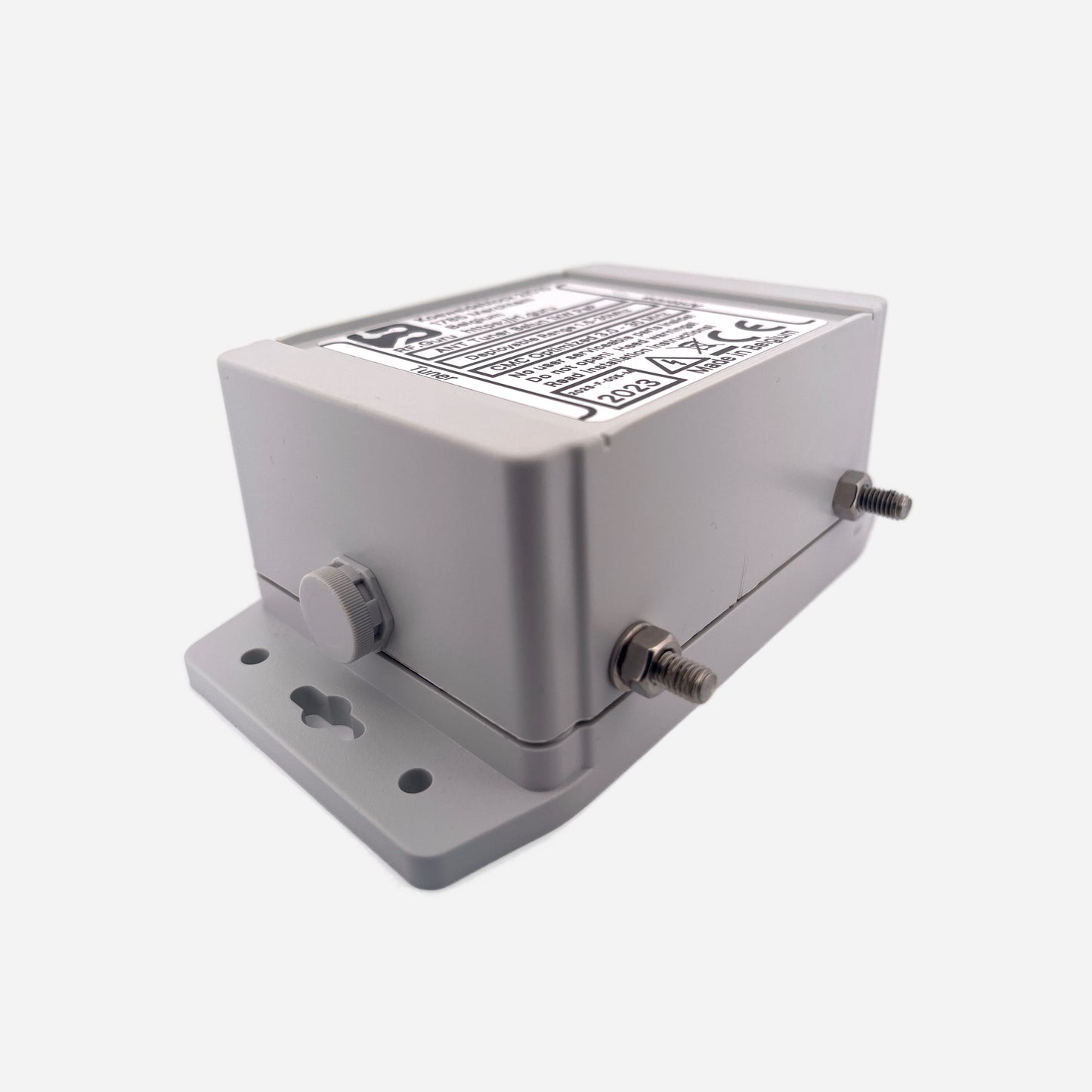
This current-balun design provides the correct balanced-to-unbalanced transition for ladder-line-fed antennas. It uses dual 61 mm ferrite cores wound with Teflon-insulated twin lead, each conductor enclosed in a Teflon sleeve (24 kV/mm) to withstand extreme voltage stress. The four M6 terminals (two for tuner output, two for balanced line) allow a direct, low-loss connection without SO-239 or coax interfaces.
The balun tolerates wide impedance swings found at tuner outputs and maintains high current isolation across its range. It can be used standalone or cascaded with a second unit for full HF coverage.
Variants
160 – 40 m Low-Band Tuner Balun (1.5 kW ICAS)
Optimized for 1.5–15 MHz, delivering high impedance and strong suppression on 160, 80 and 40 m.
| Band | Choking Impedance (Ω) | Impedance-Equivalent dB (from |Zc|) |
|---|---|---|
| 160 m | ≥ 3.5 kΩ | ≈ 42.9 dB |
| 80 m | ≥ 7.0 kΩ | ≈ 48.9 dB |
| 40 m | ≥ 8.0 kΩ | ≈ 50.1 dB |
| *Impedance-Equivalent (dB) values are computed directly from |ZCM| using a 50 Ω common-mode source reference. Real antennas almost never present 50 Ω CM, so these values represent the balun’s intrinsic suppression capability — not attenuation under load. See: Why dB Attenuation Specs on Ham Chokes Are a Mess.* | ||
30 – 10 m High-Band Tuner Balun (1.5 kW ICAS)
High-frequency version for 30–10 m balanced loops and tuner-fed doublets.
| Band | Choking Impedance (Ω) | Impedance-Equivalent dB (from |Zc|) |
|---|---|---|
| 30 m | 3.0 kΩ | 41.6 dB |
| 20 m | 2.5 kΩ | 40.0 dB |
| 17 m | 2.3 kΩ | 39.3 dB |
| 15 m | 2.1 kΩ | 38.5 dB |
| 12 m | 1.9 kΩ | 37.6 dB |
| 10 m | 1.7 kΩ | 36.7 dB |
| *Impedance-Equivalent (dB) values derived directly from |ZCM| on a 50 Ω common-mode reference. These figures represent intrinsic suppression, not the actual CM impedance of a real antenna system.* | ||
For full 1.5–30 MHz coverage, simply install the low-band + high-band baluns in series. Cascading both raises |Zc| and increases intrinsic suppression by approximately +6 dB per doubling.
Mechanical Characteristics
- Four M6 stainless terminals (tuner → balun → ladder line)
- Each terminal isolated with Teflon spacers to eliminate creepage
- Dual 61 mm ferrite toroids for thermal + magnetic headroom
- Heat-resistant Teflon twin-lead with 24 kV/mm sleeving
- INOX 316 hardware
- UV-resistant polycarbonate enclosure, IP64 sealed
- Side-mounted terminals for maximum creepage distance
- Weight: approx. 500 g
Construction Highlights
- Dual-core architecture for broadband HF choking
- High-voltage internal coating
- Fully sealed polycarbonate enclosure with silicone gasket
- All values are conservative, verified under load
Measurements follow true common-mode current injection under load. Residual current is detected with a precision probe to derive Common-Mode Rejection (CMR) in dB — the figure that matters for tuner-fed antennas.
Differential VNA tests do not measure CM behavior. Our EMC-grade dual-probe setup measures the actual CM current reduction your tuner system sees.
Mini-FAQ
-
Q: Can I connect it directly to tuner terminals?
— Yes. The four M6 posts allow direct tuner → balun → ladder line connections. -
Q: Are the terminals insulated?
— Yes. Teflon spacers prevent creepage along the enclosure surface. -
Q: Which variant do I need?
— Low-band for 160–40 m; High-band for 30–10 m loops and doublets. -
Q: Can I use both together?
— Yes. Cascading covers 1.5–30 MHz and increases suppression. -
Q: Outdoor safe?
— Fully sealed, IP64, HV-coated, and designed for harsh environments.
Interested in more technical content? Subscribe to our updates.
Questions or experiences to share? Contact RF.Guru.
Share