RF Guru
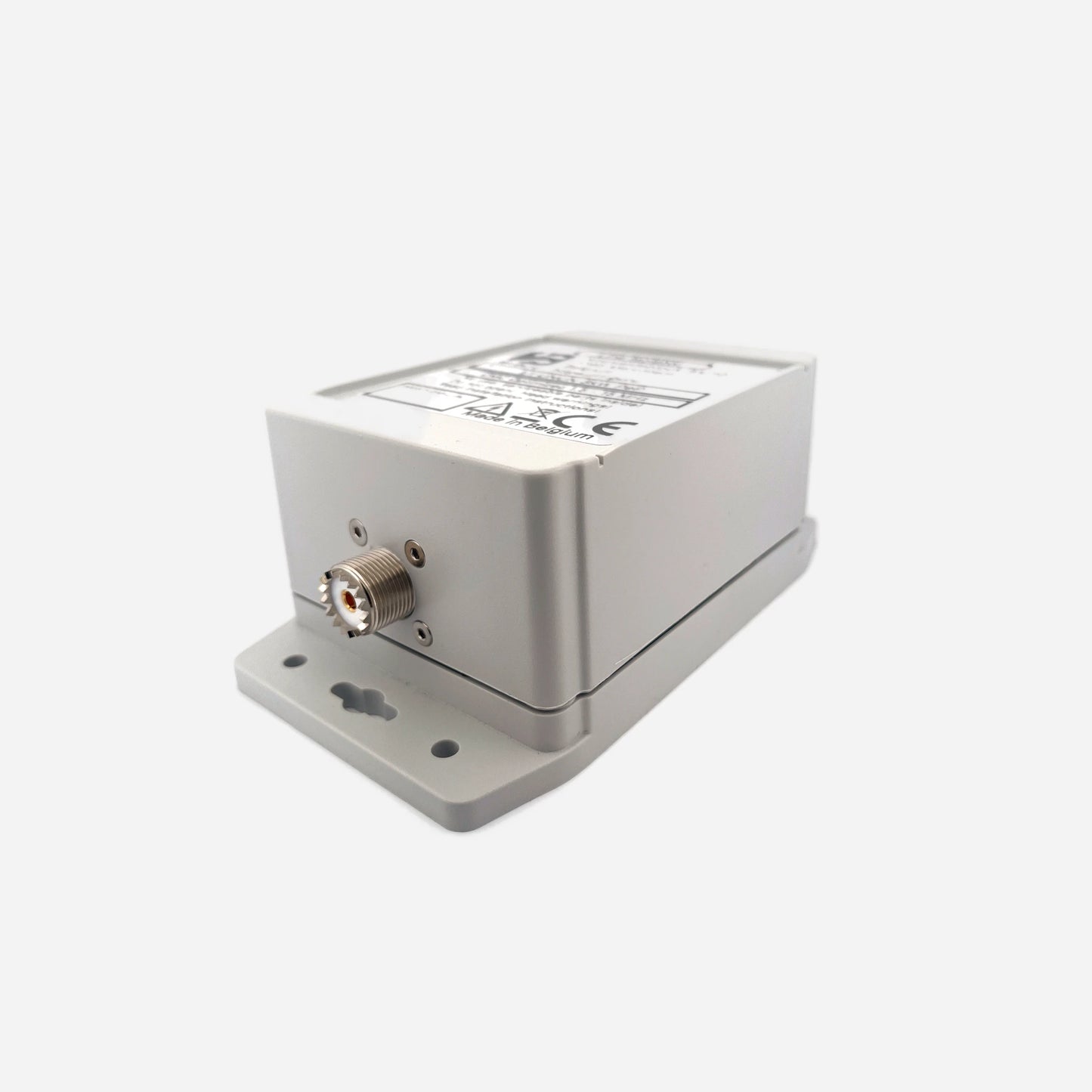
100W ICAS Single Core Wideband 160–10 m 1:1 Current Balun or Choke
100W ICAS Single Core Wideband 160–10 m 1:1 Current Balun or Choke
Couldn't load pickup availability
This is the 100 W ICAS common-mode choke of our lineup — designed for real-world 100 W transceivers, portable stations, and typical home installations. This choke delivers reliable suppression without unnecessary QRO bulk. Ratings are based on thermal and magnetic limits under worst-case common-mode excitation.
Baluns in a Nutshell
Why “Common-Mode” Is the Most Abused Term in Ham Radio
How Much Choking Do You Really Need — for RX and TX?
Purpose-Built for 100 W Stations
This choke targets the most common HF problem: uncontrolled common-mode current on the feedline. It is ideal for suppressing RF ingress, stabilizing tuners, and protecting the transceiver — without pretending that “power handling” equals forward RF wattage.
Specifications
- Coax: 5 mm PTFE coax
- Power rating (single unit): 100 W ICAS / 50–70 W CCS
- Usable bands: 160–10 m (worst case: 160–80 m)
- Connectors: PL-259 or Type-N
- Mounting: Compact outdoor or indoor enclosure
Band-by-Band Thermal Reality
| Band | Typical CM Current Limit | Safe Power Range | Status |
|---|---|---|---|
| 160 m | ≈ 0.5 A | 50–70 W | Borderline at 100 W ICAS |
| 80 m | ≈ 0.8 A | 70–100 W | Acceptable |
| 40 m | ≈ 1.2 A | 100–150 W | Safe |
| 20–10 m | ≈ 1.5–2 A | 120–200 W | Very safe |
Worst-case heating occurs on 160–80 m due to ferrite loss characteristics at low HF.
Using Multiple 100 W ICAS Chokes — The Correct Method
Common-mode suppression increases additively when chokes are distributed along the feedline, while thermal stress per choke decreases.
- 1× choke at the antenna feedpoint
- 1× choke at the station entry
- 1× choke directly at the transceiver
- ≈ 250 W ICAS equivalent for SSB / CW
- ≈ 100 W FT8 / FT4 continuous duty
Important: three chokes do not create a 300 W choke. They reduce CM current per location and improve overall field distribution.
Measured Performance — Single 100 W ICAS Choke
Measured per EMC-style common-mode injection method. Values shown are conservative real-world figures.
| Band | Choking Impedance (Ω) | Impedance-Equivalent dB (from |ZCM|) |
|---|---|---|
| 160 m | 2.5 kΩ | 34.0 dB |
| 80 m | 3.5 kΩ | 36.9 dB |
| 40 m | 5.5 kΩ | 40.8 dB |
| 30 m | 3.0 kΩ | 35.6 dB |
| 20 m | 2.2 kΩ | 32.9 dB |
| 17 m | 1.9 kΩ | 31.6 dB |
| 15 m | 1.6 kΩ | 30.1 dB |
| 12 m | 1.3 kΩ | 28.3 dB |
| 10 m | 1.0 kΩ | 26.0 dB |
| *Impedance-Equivalent (dB) values represent intrinsic suppression capability, not antenna-dependent attenuation. | ||
Measured Performance — Three 100 W ICAS Chokes in Series
Three identical chokes installed in series with ~1.5–2 m coax spacing. Total common-mode impedance increases approximately 3×.
| Band | Choking Impedance (Ω) | Impedance-Equivalent dB (from |ZCM|) |
|---|---|---|
| 160 m | 7.5 kΩ | 43.5 dB |
| 80 m | 10.5 kΩ | 46.4 dB |
| 40 m | 16.5 kΩ | 50.4 dB |
| 30 m | 9.0 kΩ | 45.1 dB |
| 20 m | 6.6 kΩ | 42.4 dB |
| 17 m | 5.7 kΩ | 41.1 dB |
| 15 m | 4.8 kΩ | 39.6 dB |
| 12 m | 3.9 kΩ | 37.8 dB |
| 10 m | 3.0 kΩ | 35.6 dB |
| *Series installation reduces common-mode current at each location and spreads thermal load. | ||
When This Choke Is Ideal
- 100 W transceivers
- EFHW / EFOC antennas
- OCF dipoles and low doublets
- Verticals with limited radials
- POTA / portable stations
When to Step Up
For legal-limit amplifiers, extreme imbalance, or continuous high-duty operation on 160–80 m, a dual-core or large-aperture QRO choke is the correct solution. Ferrite volume ultimately sets the absolute CM current limit.
Mini-FAQ
-
Q: Is 100 W ICAS realistic?
— Yes. It is conservative and assumes worst-case common-mode conditions. -
Q: Can I run FT8 at 100 W?
— Yes, especially with two or three chokes distributed along the feedline. -
Q: Why does placement matter?
— Because common-mode current peaks differ along the feedline.
Interested in more technical content? Subscribe to our updates.
Questions or experiences to share? Contact RF.Guru.
Share