

RF Guru
5kW ICAS Quad Core High Bands 30–10 m QRO 1:1 Current Balun or Choke
5kW ICAS Quad Core High Bands 30–10 m QRO 1:1 Current Balun or Choke
Couldn't load pickup availability
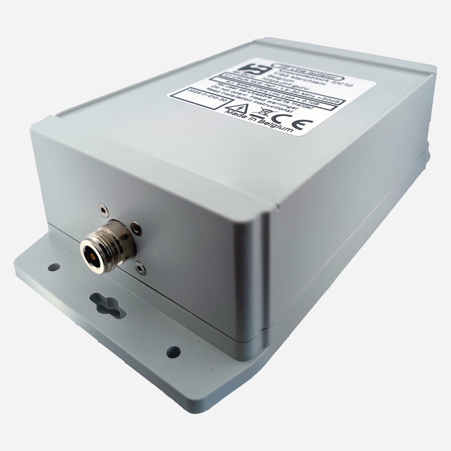
This is the quad-core compact QRO version of our broadband choke series — designed for high-duty HF operation using four stacked 2.4″ toroids arranged as two dual-core sections in series. It offers outstanding high-frequency isolation, low insertion loss, and robust power handling for both amplifier outputs and antenna feedpoints. The choke is enclosed in a HV-coated polycarbonate housing with custom silicone gaskets and a decompression valve for long-term outdoor service. All data are measured under load — no simulations.
Baluns in a Nutshell
Why “Common-Mode” Is the Most Abused Term in Ham Radio
How Much Choking Do You Really Need — for RX and TX?
Purpose-Built for Heavy-Duty HF Service
This quad-core configuration offers exceptional wideband suppression and generous thermal headroom. It is ideal at amplifier outputs, station entry points, or directly at the antenna feedpoint to maximize common-mode rejection across the 30–10 m spectrum.
Specifications
- Core configuration: 4 × 2.4″ toroids (two dual stacks in series)
- Winding: 4 turns of high-temperature coax per section
- Power rating (PL-259): ≈ 3 kW PEP / 1.5 kW CCS continuous
- Power rating (N-type): up to 5 kW ICAS under 50 Ω load (ICAS rating applies to N connector only)
- Connectors: PL-259 / SO-239 / N-type (N recommended for high-duty use)
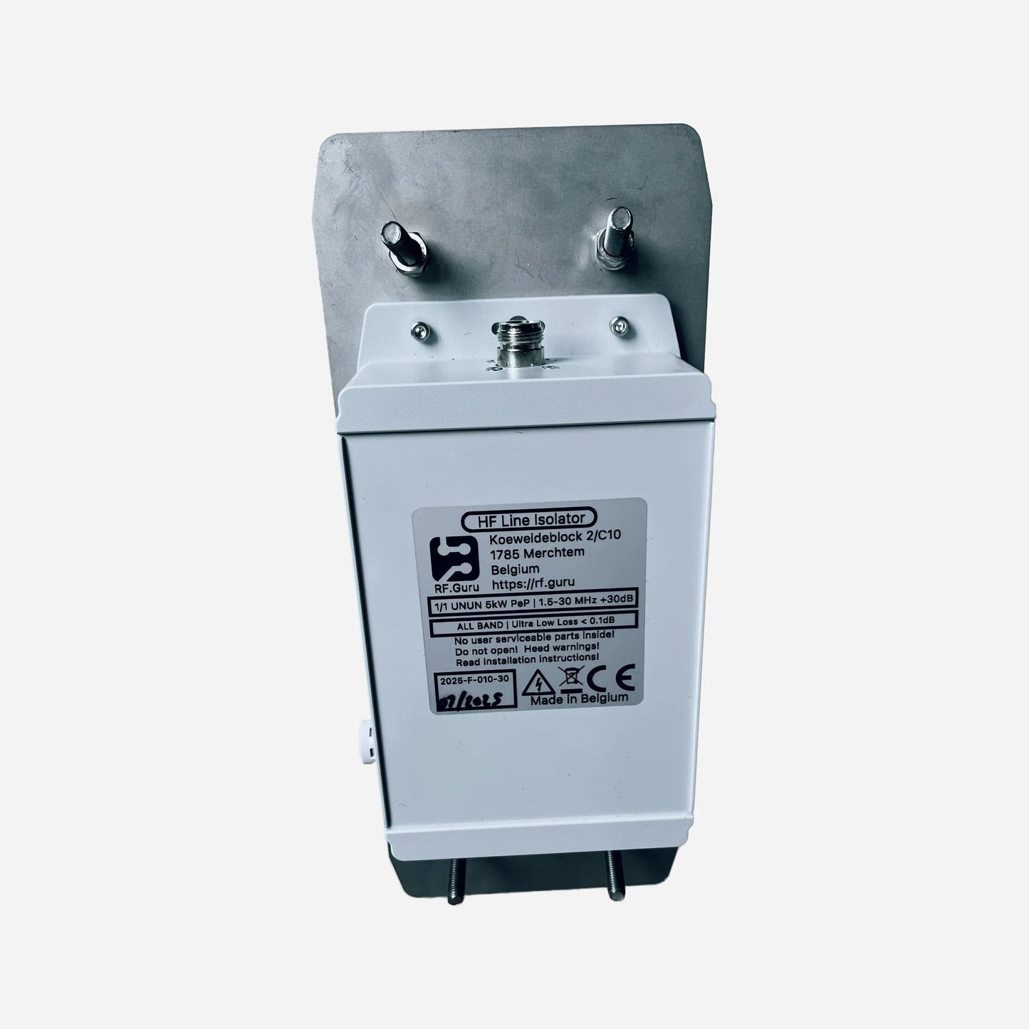
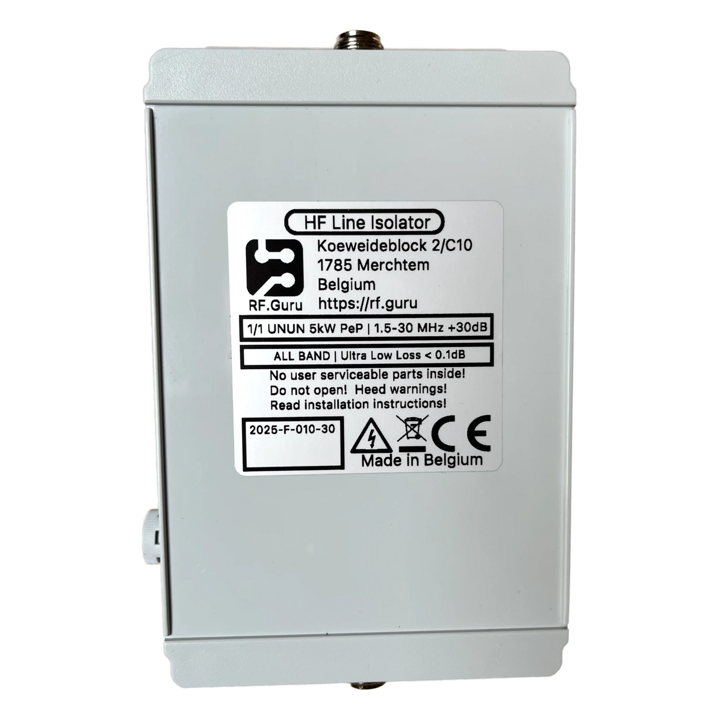
- Enclosure: HV-coated polycarbonate, silicone gaskets, decompression valve
- Reference @ 50 Ω: Vpk ≈ 700 V, Vrms ≈ 500 V, Ipk ≈ 14 A, Irms ≈ 10 A
Measured Performance (Quad-Core, Two Stacks in Series)
Measured per EMC-standard procedure with controlled common-mode current injection and precision sensing under load.
| Band | Choking Impedance (Ω) | Common-Mode Rejection (dB) |
|---|---|---|
| 30 m | 14.21 kΩ | 55.1 dB |
| 20 m | 16.63 kΩ | 56.5 dB |
| 17 m | 6.39 kΩ | 48.2 dB |
| 15 m | 4.51 kΩ | 45.1 dB |
| 12 m | 3.35 kΩ | 42.6 dB |
| 10 m | 2.73 kΩ | 40.8 dB |
Excellent wideband isolation from 30 m through 10 m. For extended low-band coverage, combine with a 160–40 m choke in series for ≈ +30 dB extra CMR below 10 MHz.
Installation Guidance
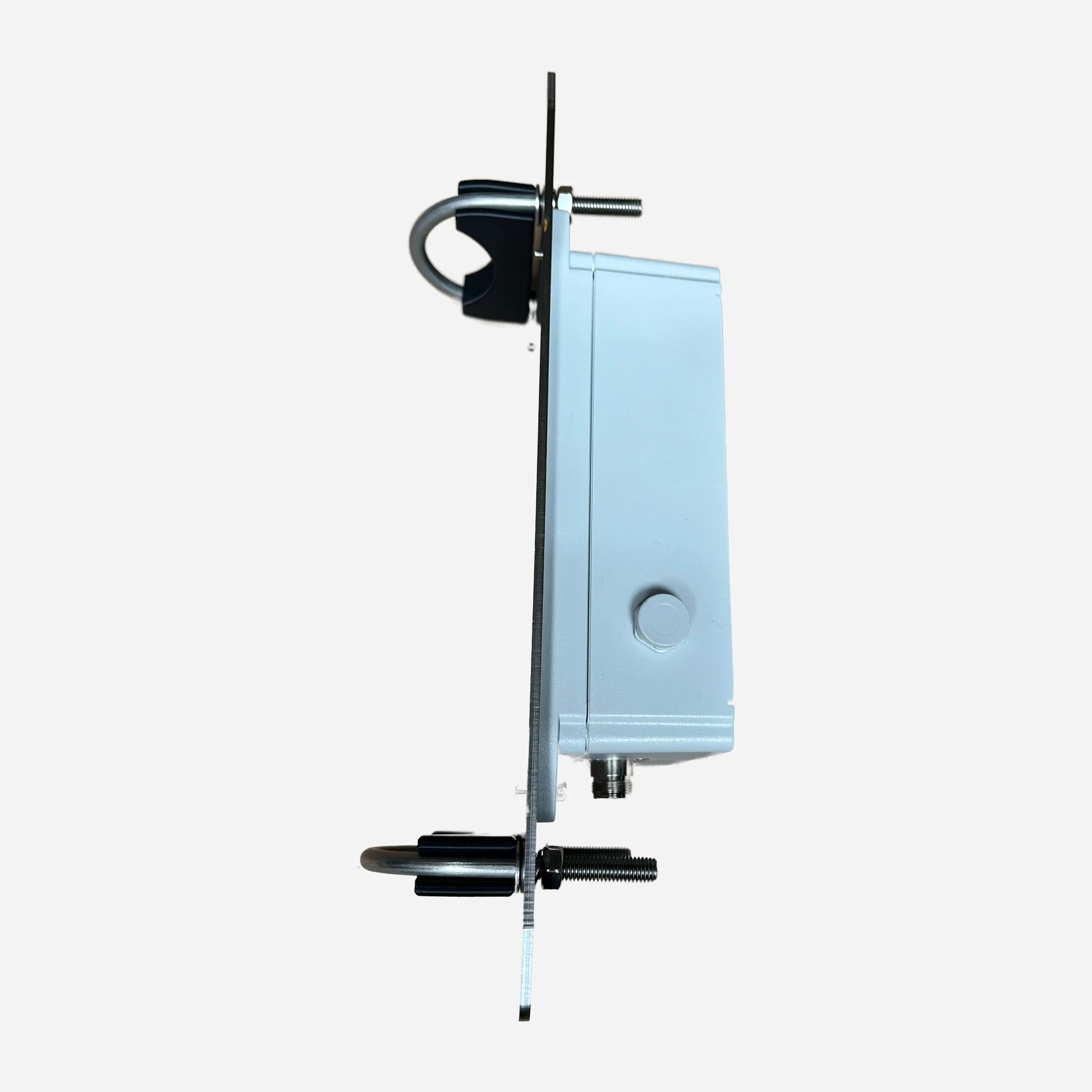
- Install at the amplifier output, station entry, or antenna feedpoint to suppress common-mode currents and increase system immunity.
- Mount horizontally or vertically — the housing is sealed and pressure-equalized for outdoor use.
- All ratings reflect conservative real-world measurements under continuous carrier load.
All RF.Guru Lab chokes are evaluated using the EMC common-mode method with dual probes — one injects a calibrated current into the outer conductor, the other measures the residual current beyond the choke. This directly yields Common-Mode Rejection (CMR) in dB, representing true shield suppression under operating conditions.
Differential VNA sweeps cannot show this behavior; the EMC method follows recognized standards and captures real RF performance on the coax shield.
Mini-FAQ
-
Q: What makes this a “quad-core” choke?
— It uses two dual-core sections in series to double the choking impedance and thermal capacity. -
Q: Can it replace two separate units?
— Yes, it offers comparable rejection to two dual-core chokes combined for mid-to-high HF use. -
Q: What power levels can it handle?
— With PL connectors, about 3 kW PEP / 1.5 kW CCS. With N-type connectors, up to 5 kW ICAS. ICAS rating applies only to the N connector version. -
Q: Where should I install it?
— At the amplifier output, station entry, or directly at the antenna feedpoint for best results. -
Q: Are these figures theoretical?
— No — all values are measured using calibrated EMC probes under load.
Interested in more technical content? Subscribe to our updates for deep-dive RF articles and lab notes.
Questions or experiences to share? Contact RF.Guru.
Share