RF Guru
10kW CCS Dual Core Wideband 160–10 m QRO 1:1 Current Balun or Choke
10kW CCS Dual Core Wideband 160–10 m QRO 1:1 Current Balun or Choke
Couldn't load pickup availability
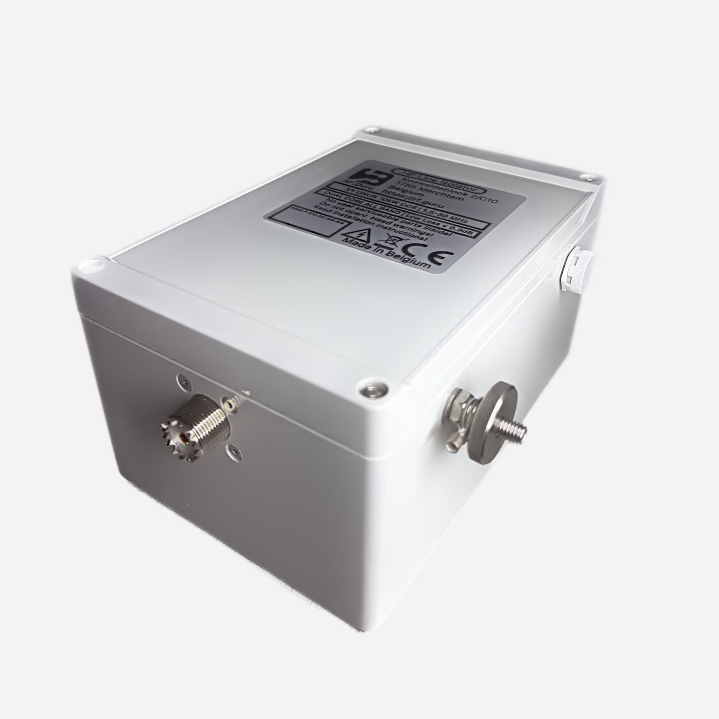
This is the industrial-grade version of our dual-core line — built for operators running continuous high-duty cycles and legal-limit amplifiers. Constructed around two massive 4″ (≈ 10.2 cm) ferrite toroids with a wide-aperture winding, this choke delivers up to 10 kW CCS when fitted with 7/16 DIN connectors. Encased in a polycarbonate HV-coated enclosure with custom silicone gaskets and a decompression valve, it’s designed to thrive through contest weekends, salt air, and the toughest QRO environments. All performance figures are conservative real-world measurements, not simulations.
Baluns in a Nutshell
Why “Common-Mode” Is the Most Abused Term in Ham Radio
How Much Choking Do You Really Need — for RX and TX?
Purpose-Built for Amplifier-Level Duty
This wideband choke is the go-to model for amplifier outputs and station entry points. It safely handles extreme RF voltages and currents at low frequencies while maintaining excellent linearity. Two units in series, spaced by ~2 m of coax, yield full 10 kW CCS capability on 160–40 m with strong isolation. 10 kW CCS operation is limited to 160–40 m, with 40 m borderline.
Specifications
- Model: 2× 4″ (10.2 cm) ferrite toroids
- Winding: 11 turns of high-temperature coax
- Power rating: 10 kW PEP / 10 kW CCS (with 7/16 DIN)
- Connectors: PL-259, N-type, or 7/16 DIN
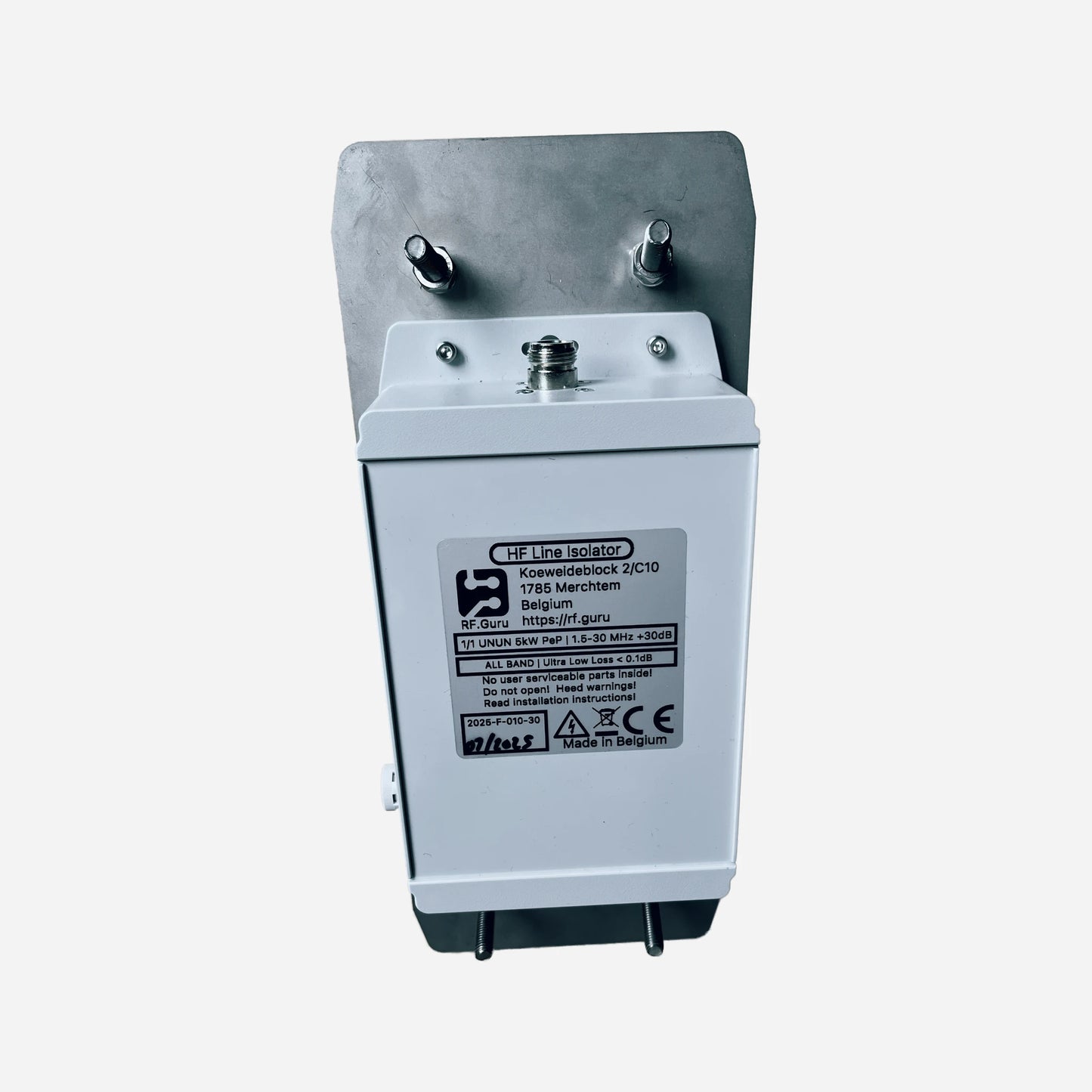
- Enclosure: HV-coated polycarbonate, silicone gaskets, decompression valve
- Reference @ 50 Ω: Vpk 1000 V, Vrms 707 V, Ipk 20 A, Irms 14.1 A
Measured Performance (Single Unit)
Measured per EMC-standard method using injected and sensed common-mode currents. Values shown are conservative and verified under load.
| Band | Choking Impedance (Ω) | Impedance-Equivalent dB (from |Zc|) |
|---|---|---|
| 160 m | 12.0 kΩ | 53.6 dB |
| 80 m | 16.0 kΩ | 56.1 dB |
| 40 m | 6.0 kΩ | 47.6 dB |
| 30 m | 2.0 kΩ | 38.1 dB |
| 20 m | 1.6 kΩ | 36.1 dB |
| 17 m | 1.4 kΩ | 35.0 dB |
| 15 m | 1.2 kΩ | 33.6 dB |
| 12 m | 1.0 kΩ | 32.0 dB |
| 10 m | 0.8 kΩ | 30.1 dB |
| *Impedance-Equivalent (dB) values are computed directly from measured |ZCM| using a 50 Ω common-mode source reference. Real antennas seldom present 50 Ω in common-mode, so these values represent the choke’s intrinsic suppression capability, not the attenuation you would see under a specific antenna load. More background: Why dB Attenuation Specs on Ham Chokes Are a Mess. | ||
If your focus is 30–10 m, our Quad-Core High-Bands choke provides >40 dB intrinsic suppression across the upper HF range. Alternatively, installing two standard chokes in series doubles |Zc| and increases suppression by approximately +6 dB.
Comparison — Standard vs Heavy-Duty QRO Chokes
| Feature | Standard Dual-Core QRO Chokes | Heavy-Duty Wideband QRO Choke |
|---|---|---|
| Core Size | 2.4″ (6.1 cm) | 4″ (10.2 cm) |
| Ferrite Mass | Standard HF grade | 3.5× more ferrite volume |
| Power Rating (ICAS) | Up to 9 kW PEP | 10 kW PEP / 10 kW CCS |
| Primary Use | General station suppression | Amplifier output / station entry QRO |
| Optimum Bands | 160–10 m (dual models) | 160–30 m strong, usable to 10 m |
| Connector Options | PL-259 / N-type | PL-259 / N-type / 7/16 DIN |
| Typical Installation | Antenna feedpoint or transition | After PA / outside shack |
Maximum ICAS/CCS Power Ratings
| Connector Type | 160–40 m Band | 30–10 m Band | 6–2 m Band | Limiting Factor |
|---|---|---|---|---|
| PL-259 / UHF | ≈ 2.7 kW ICAS | ≈ 1.3 kW ICAS | ≈ 0.6 kW ICAS | Connector |
| Type-N | ≈ 10 kW CCS* | ≈ 5 kW ICAS | ≈ 2 kW ICAS | Coax |
| 7/16 DIN | ≈ 10 kW CCS* | ≈ 5 kW ICAS | ≈ 2 kW ICAS | Coax |
*For full 10 kW CCS operation, install two units in series with Type-N or 7/16 DIN connectors and ~2 m of coax spacing. Use dual vent ports instead of a single decompression valve.
Installation Guidance
- Place one choke directly after the PA and one at the station entry point.
- Maintain 1.5–2 m of coax between units for maximum suppression.
- Mount horizontally or vertically — the enclosure is fully sealed and pressure-equalized.
- All impedance and dB values are conservative and measured under load.
At RF.Guru Lab, all baluns are evaluated using EMC-standard dual-probe common-mode testing. One probe injects controlled common-mode current into the device under test, while a second probe measures the resulting CM current at the output.
This method reveals the choke’s true common-mode suppression under real load conditions — including high voltage, reactive behaviour, and typical coax geometries — without differential-mode contamination.
Typical VNA “shield-to-shield” tests excite the feedline in differential mode and do not measure true CM behaviour. Our EMC method captures actual CM suppression as it happens on tuner-fed and PA-fed HF systems.
Mini-FAQ
-
Q: How does this differ from the standard dual-core chokes?
— It uses larger 4″ ferrites for higher magnetic volume, voltage tolerance, and full continuous-duty capability. -
Q: Can I use it alone?
— Yes. But two in series, spaced by ~2 m of coax, provide maximum suppression for high-power stations. -
Q: Why do the high-band values drop?
— #31 ferrite is optimized for low/mid HF. For 17–10 m, the Quad-Core High-Bands choke is recommended. -
Q: Connector options?
— PL-259, Type-N, or 7/16 DIN (recommended for QRO/CCS service). -
Q: Are these values theoretical?
— No. All numbers are conservative, measured under load with calibrated EMC probes.
Interested in more technical content? Subscribe to our updates for deep-dive RF articles and lab notes.
Questions or experiences to share? Contact RF.Guru.
Share