RF Guru
10kW ICAS Quad-Core 160–10 m Wideband QRO 1:1 Current Balun or Choke
10kW ICAS Quad-Core 160–10 m Wideband QRO 1:1 Current Balun or Choke
Couldn't load pickup availability
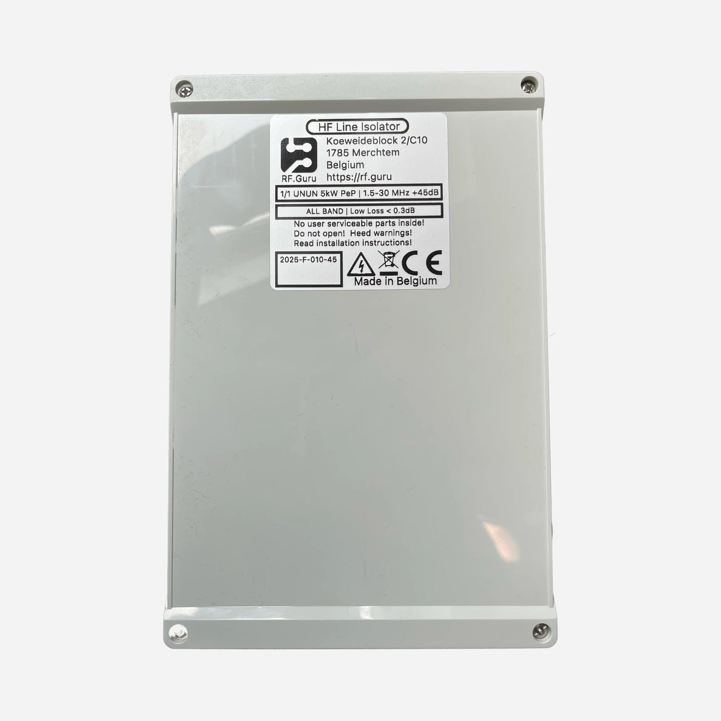
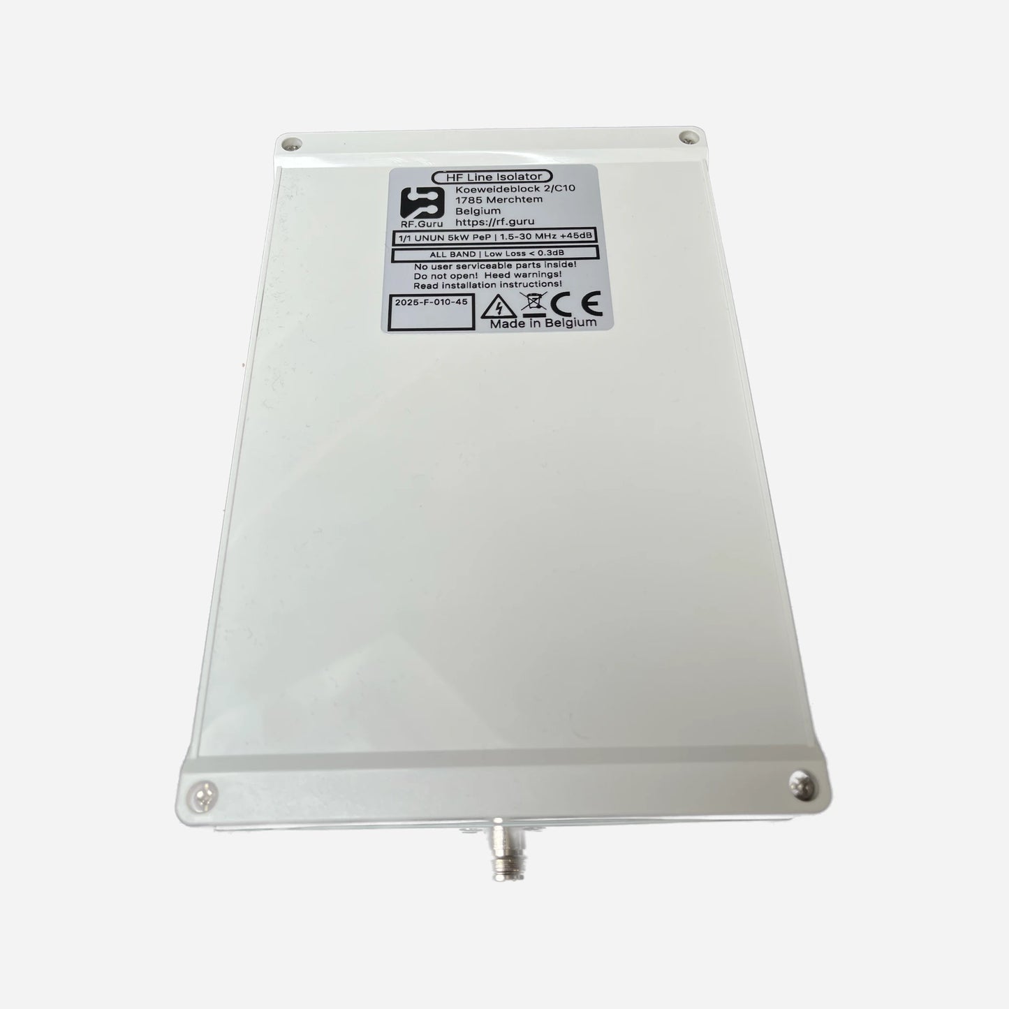
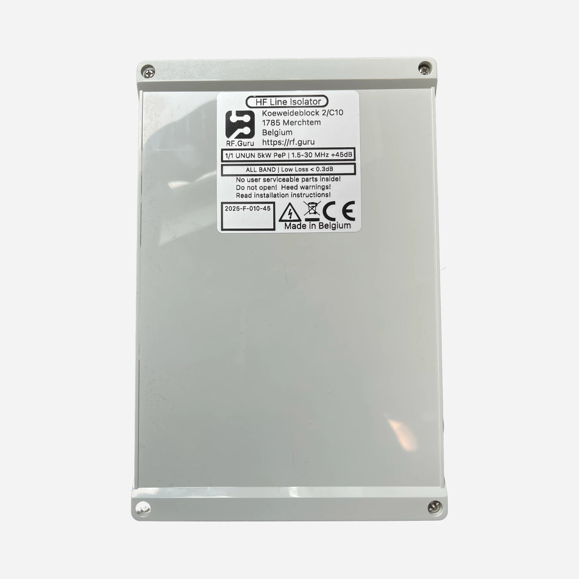
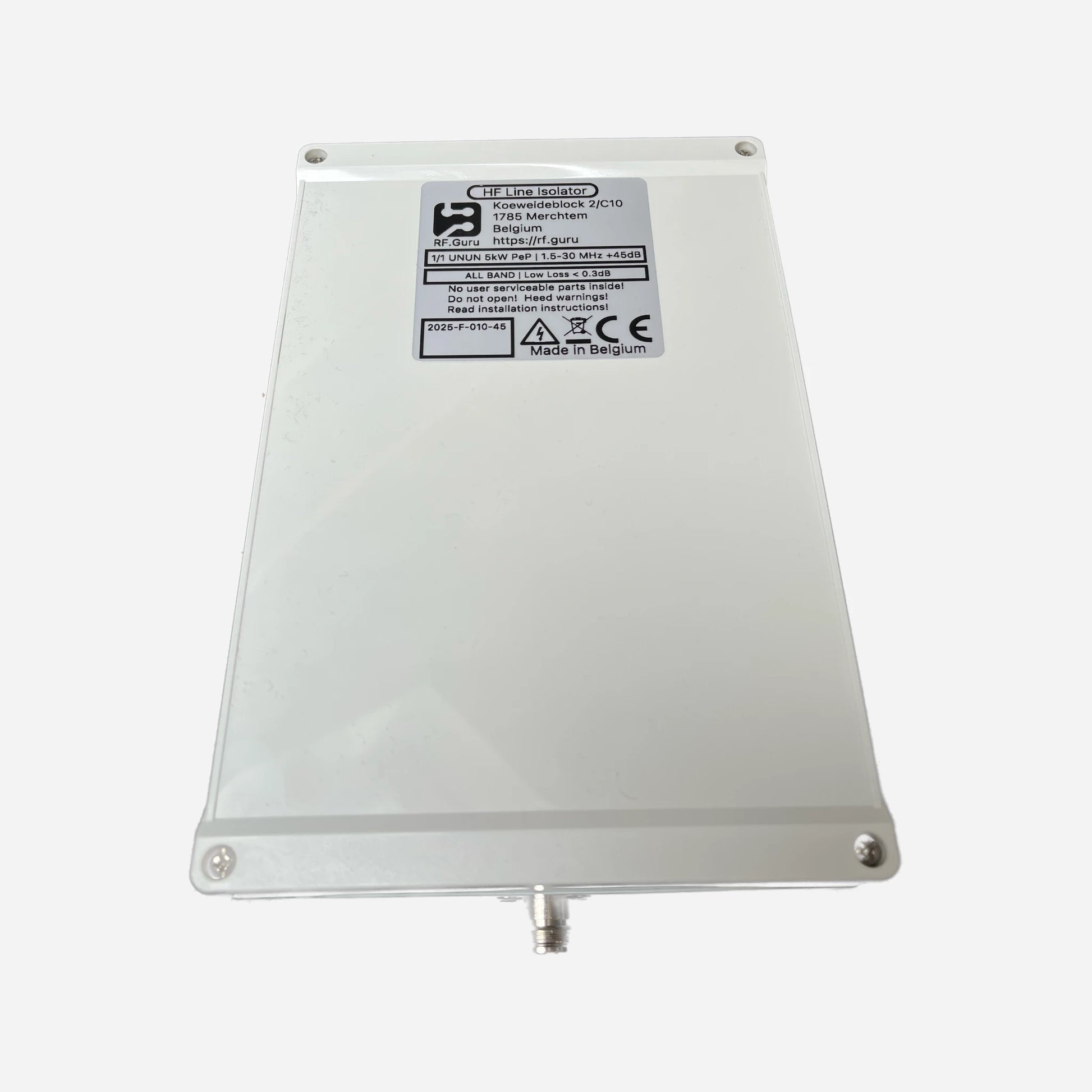
The ultimate integrated station choke for high-power HF systems. Built around four massive 4″ (10.2 cm) ferrite cores in a single enclosure, this choke provides exceptional wideband suppression with more than 36 dB Impedance-Equivalent attenuation (from |Zc|) from 1.8 MHz through 30 MHz. Designed for 10 kW PEP operation on 7/16 DIN connectors, or up to 5 kW PEP with N-type or PL-259. Encased in a polycarbonate HV-coated housing with custom gaskets and decompression valve — engineered for lifelong QRO duty.
Baluns in a Nutshell
Why “Common-Mode” Is the Most Abused Term in Ham Radio
How Much Choking Do You Really Need — for RX and TX?
The Ultimate Shack-Side Isolation
This choke belongs immediately after your power amplifier, where it stops residual RF from re-entering the shack. It forms the top tier in the RF.Guru choke chain:
- 1️⃣ Inside the shack: This quad-core wideband choke (PA-behind).
- 2️⃣ Outside the shack: One dual 4″ choke for external suppression.
- 3️⃣ At the feedpoint: Band-specific QRO chokes for final current balancing.
When multiple chokes are installed in series, their impedances add. Each doubling of total |Zc| yields ≈ +6 dB intrinsic suppression.
Specifications
- Core assembly: Four stacked 4″ (10.2 cm) ferrite cores
- Frequency range: 1.8–30 MHz (160–10 m)
- Impedance-Equivalent Suppression: > 36 dB (from |Zc|, 50 Ω CM reference)
- Choking impedance: up to 24–32 kΩ on the low bands
- Power handling: 10 kW PEP (7/16 DIN); 5 kW PEP (N/PL)
- Enclosure: HV-coated polycarbonate, gaskets, decompression valve
- Environment: UV-resistant, sealed, pressure-equalized
Measured Performance (Quad-Core Assembly)
Measured using industry-standard EMC common-mode injection and sensing.
| Band | Choking Impedance (Ω) | Impedance-Equivalent dB (from |Zc|) |
|---|---|---|
| 160 m | 24.0 kΩ | 59.6 dB |
| 80 m | 32.0 kΩ | 62.1 dB |
| 40 m | 12.0 kΩ | 53.6 dB |
| 30 m | 4.0 kΩ | 44.1 dB |
| 20 m | 3.2 kΩ | 42.1 dB |
| 17 m | 2.8 kΩ | 41.0 dB |
| 15 m | 2.4 kΩ | 39.6 dB |
| 12 m | 2.0 kΩ | 38.1 dB |
| 10 m | 1.6 kΩ | 36.1 dB |
| *Impedance-Equivalent (dB) values are computed directly from measured |ZCM| using a 50 Ω common-mode source reference. Real antennas almost never present 50 Ω in common-mode, so these values represent the choke’s intrinsic suppression capability — not the attenuation of a specific antenna installation. More details: Why dB Attenuation Specs on Ham Chokes Are a Mess.* | ||
Maximum ICAS/CCS Power Ratings
| Connector Type | 160–40 m Band | 30–10 m Band | 6–2 m Band | Limiting Factor |
|---|---|---|---|---|
| PL-259 / UHF | ≈ 2.7 kW ICAS | ≈ 1.3 kW ICAS | ≈ 0.6 kW ICAS | Connector |
| Type-N | ≈ 10 kW ICAS | ≈ 5 kW ICAS | ≈ 2 kW ICAS | Coax |
| 7/16 DIN | ≈ 10 kW ICAS | ≈ 5 kW ICAS | ≈ 2 kW ICAS | Coax |
Installation Guidance
- Install immediately after the power amplifier for maximum CM suppression.
- Use a second choke outside the shack and a third at the feedpoint for full-chain protection.
- Mount horizontally or vertically — the enclosure is sealed and pressure-equalized.
- All ratings reflect conservative, real-world CCS/ICAS measurements.
At RF.Guru Lab, all chokes are measured using EMC-standard dual-probe common-mode testing. One probe injects controlled CM current into the device under test, while a second probe measures the resulting CM current at the output.
This yields a true Common-Mode Rejection (CMR) curve based on actual current reduction — not the differential-mode impedance seen in shield-to-shield VNA tests.
Typical VNAs excite the coax in differential mode, which does not measure CM behaviour. Our EMC method directly quantifies real CM suppression under load, identical to PA- and tuner-fed systems.
Mini-FAQ
-
Q: What makes this different from the dual 4″ choke?
— It uses twice the ferrite volume in one enclosure for higher flux tolerance and wideband suppression. -
Q: Where should I install it?
— Directly behind the power amplifier, before any switch matrix or tuner. -
Q: What connectors are available?
— 7/16 DIN for 10 kW PEP, or N / PL-259 for up to 5 kW PEP. -
Q: Outdoor-rated?
— Yes. Fully sealed, UV-resistant, and pressure-equalized. -
Q: Are these values theoretical?
— No. All suppression data are load-tested using calibrated EMC probes.
Interested in more technical content? Subscribe to our updates for deep-dive RF articles and lab notes.
Questions or experiences to share? Contact RF.Guru.
Share


