RF Guru
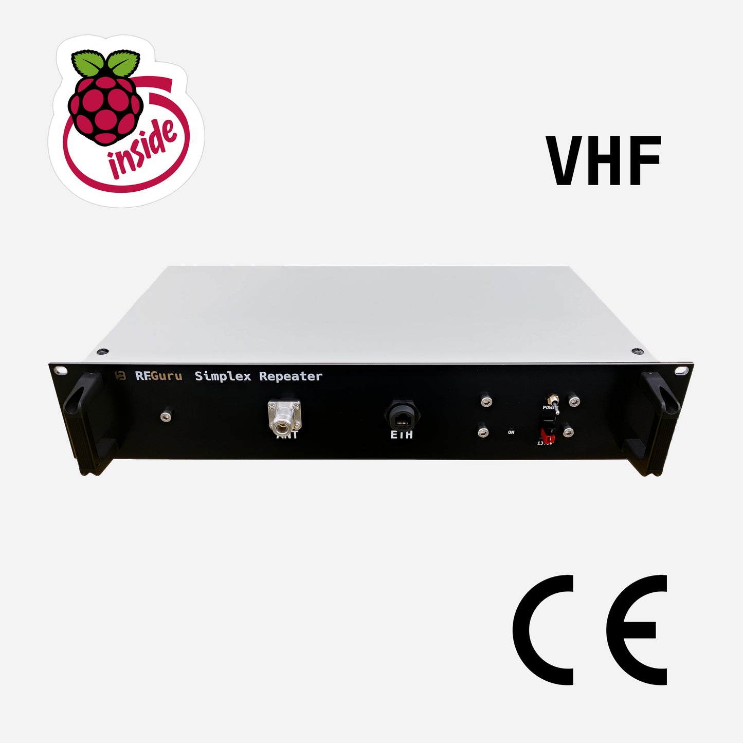
19" 2U Rack Mountable Analog Simplex Repeater 2m VHF 30W
19" 2U Rack Mountable Analog Simplex Repeater 2m VHF 30W
Couldn't load pickup availability
19" Rack-Mountable Analog Simplex Repeater
The Analog Repeater Module is a compact, CE-marked system for building reliable SVXLink simplex repeaters, EchoLink gateways, and other analog linking or bridging solutions.
The latest revision is based on our new Pi 4 architecture and incorporates improved heat spreading and thermal dissipation for greater stability during sustained operation. It is built into a shielded 2U 19" rack-mount enclosure for clean, dependable fixed-station use.
The RF chain now includes a 144–146 MHz transmit/receive narrow band-pass filter on the antenna side of the RF power-amplifier stage. This high-Q, low-loss filter suppresses out-of-band signals while maintaining approximately 0.25 dB measured insertion loss across the 2 m passband.
Currently, an SVXLink Bookworm image is available for SVXLink and EchoLink use.
What Makes the Repeater Module Different
- New Pi 4 architecture — updated processing platform with improved heat spreading and thermal dissipation for stable sustained operation.
- External RF via N connector — VHF RF is brought out to an external N connector for a clean and durable RF interface.
- ≈30 W RF output (≈44.8 dBm).
- Post-amplifier narrow band-pass filtering — an integrated 144–146 MHz filter provides strong out-of-band rejection with approximately 0.25 dB measured passband insertion loss.
- Dedicated low-noise 5 V rail — an integrated RF.Guru 12–24 V-to-5 V converter supplies up to 3 A to the transceiver module, with output ripple specified below 15 mVpp under load.
- Bidirectional common-mode suppression — Würth WE-STAR-TEC snap-on ferrites help reduce cable-borne RF and noise entering or leaving the enclosure through the PA, Ethernet, and USB power cable paths.
- 13.8 V input energy reservoir — a 10,000 µF, 25 V Würth electrolytic capacitor helps limit momentary rail droop and ripple when the transmitter keys.
Specs at a Glance
| Feature | Specification |
|---|---|
| Transceiver Platform | VHF (134–174 MHz) |
| Filtered Operating Band | 2 m (144–146 MHz) |
| RF Output Power | ≈44.8 dBm (≈30 W) |
| Receiving Sensitivity | −124 dBm at 12 dB SINAD |
| Output Filter | 144–146 MHz post-amplifier TX/RX narrow BPF; ≈0.25 dB insertion loss |
| Bandwidth | 12.5 kHz / 25 kHz |
| Architecture | RF.Guru Pi 4 architecture with improved thermal dissipation |
| Nominal DC Input | 13.8 V DC |
| 5 V Transceiver Supply | RF.Guru low-noise 13.8-to-5 V converter; 3 A maximum; <15 mVpp ripple |
| Common-Mode Suppression | Würth snap-on ferrites on PA, Ethernet, and USB power paths |
| 13.8 V Input Reservoir | Würth 10,000 µF / 25 V input reservoir capacitor |
| Clock Stability | 1 ppm KDS TCXO |
| Audio | Wolfson WM8960 ADC / 1 W DAC (48 kHz) |
| RF Connector | N connector |
| Compliance | CE marked — complete assembled system |
Included with the Product
- Complete assembled and tested device
- Preloaded storage with our latest image
Key Features
- New Pi 4–based RF.Guru architecture
- Improved heat spreading and thermal dissipation for greater stability during sustained operation
- Fully shielded 19" enclosure engineered for RF-tight repeater service
- Integrated post-amplifier 144–146 MHz narrow band-pass filter for clean transmit and receive performance
- ENIG-finished PCB (Electroless Nickel Immersion Gold)
- Ultra-stable 1 ppm TCXO
- Multi-stage power-integrity and conducted-noise control using feedthrough capacitors, a dedicated RF/EMI-filtered 5 V converter, Würth snap-on ferrites, and a 10,000 µF input energy reservoir
Power Integrity and Common-Mode Suppression
The transceiver module is powered by an integrated RF.Guru Ultra-Low-Noise USB Power Supply. It derives a regulated 5 V rail at up to 3 A from the repeater's nominal 13.8 V input. The converter module itself accepts 12–24 V DC, but the complete repeater remains a nominal 13.8 V system. Output ripple is specified below 15 mVpp under load, and an additional EMI-filter stage helps limit conducted-noise coupling between the main DC wiring and the sensitive 5 V rail. This is RF/EMI filtering rather than safety-rated galvanic isolation.
Würth Elektronik WE-STAR-TEC snap-on ferrites provide additional cable-borne common-mode suppression on the PA, Ethernet, and USB power cable paths. Configured around the relevant cable conductor sets, they add high-frequency impedance to unwanted common-mode currents in both directions. This helps reduce external RF and noise entering the enclosure and limits internally generated RF noise conducted onto external cabling.
A 10,000 µF, 25 V Würth WCAP-ATG8 aluminum electrolytic capacitor is fitted across the 13.8 V input as a bulk energy reservoir. When the power amplifier keys, the transmit current rises rapidly. The capacitor supplies part of this brief current step locally while the upstream supply and cabling settle, helping reduce transient input-voltage sag and short-duration ripple while keeping the transceiver and control rails stable during the receive-to-transmit transition.
Power Consumption
- Typical (indicative): ~3 W RX / ~112 W TX
Software - How-To - Instructions
VHF Version Measurements
Sensitivity Measurements
Receiver sensitivity is −124 dBm, specified at 12 dB SINAD. This provides a practical indication of weak-signal receive performance.
Integrated 144–146 MHz Narrow Band-Pass Filter
A 144–146 MHz transmit/receive narrow band-pass filter is installed on the antenna side of the RF power-amplifier stage. Its high-Q coils and capacitors are carefully adjusted for low loss on both transmit and receive, with approximately 0.25 dB measured insertion loss across the passband. The filter strongly suppresses out-of-band energy from HF, 6 m, 4 m, FM broadcast, and 70 cm signals, helping to reduce TVI and nearby-transmitter interference while protecting the receiver.
The following measured S21 results characterize this filter design:
| Frequency | Measured S21 |
|---|---|
| 1.8 MHz | −106 dB |
| 3.8 MHz | −110 dB |
| 7.1 MHz | −110 dB |
| 14.1 MHz | −105 dB |
| 21.2 MHz | −101 dB |
| 28.4 MHz | −94 dB |
| 50 MHz | −76 dB |
| 52 MHz | −75 dB |
| 54 MHz | −73 dB |
| 70 MHz | −64 dB |
| 70.5 MHz | −64 dB |
| 88 MHz | −53 dB |
| 98 MHz | −46 dB |
| 108 MHz | −39 dB |
| 144–146 MHz | −0.25 dB |
| 288 MHz | −60 dB |
| 432.1 MHz | −36 dB |
| 440 MHz | −44 dB |
Measured 2 m passband insertion loss: approximately 0.25 dB across 144–146 MHz.
Compliance Measurements
The complete assembled repeater system is CE marked. Measurements were conducted with a calibrated Vector Network Analyzer (VNA) and a 36 dB attenuator. Worst-case harmonic performance measured −53.07 dBc on the second harmonic, providing more than 10 dB margin relative to the applicable CE requirements.
The spectrum confirms clean transmission within 12.5 kHz bandwidth and strong suppression of unwanted emissions.
Spectrum

Harmonics

Channel Power

Mini-FAQ
- Is the complete system CE marked? — Yes. The complete assembled repeater is CE marked.
- Which band is supported here? — The transceiver platform covers 134–174 MHz; the integrated post-amplifier narrow filter defines this model's intended operating band as 144–146 MHz.
- What output power is available? — The RF output is approximately 30 W (≈44.8 dBm).
- What RF connector is used? — The module uses an external N connector.