RF Guru
1kW ICAS Quad Core VHF-UHF QRO 1:1 Current Balun or Choke
1kW ICAS Quad Core VHF-UHF QRO 1:1 Current Balun or Choke
Couldn't load pickup availability
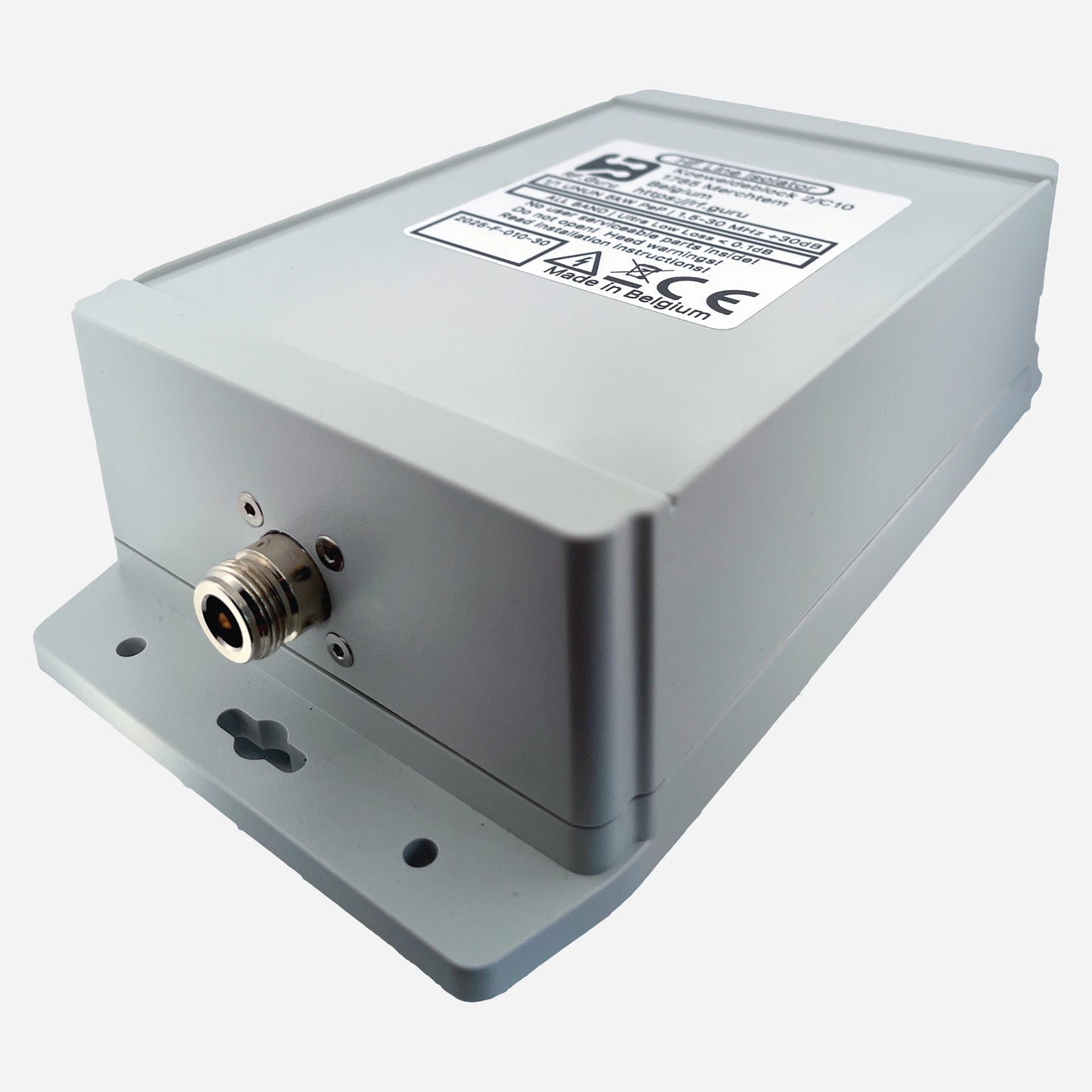
This is the quad-core compact QRO version of our broadband choke series — designed for high-duty operation using four stacked 2.4″ toroids arranged as two dual-core sections in series. It offers outstanding wideband isolation, low insertion loss, and robust power handling for both amplifier outputs and antenna feedpoints. The choke is enclosed in a HV-coated polycarbonate housing with custom silicone gaskets and a decompression valve for long-term outdoor service. All data are measured under load — no simulations.
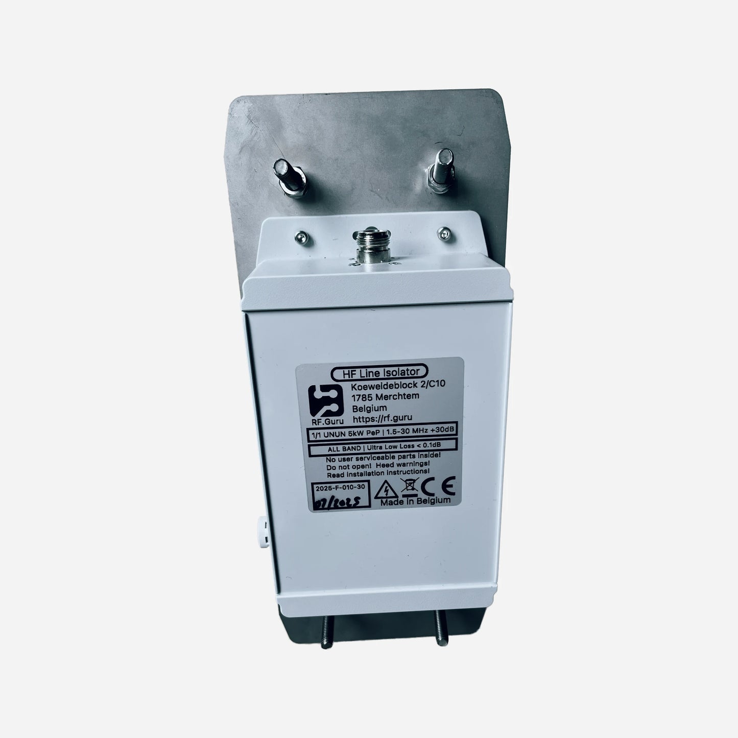
This choke has an explicit antenna direction marking on the enclosure. Follow that marking during installation — on wideband, high-isolation chokes the internal geometry and section ordering matter, and mounting it backwards can measurably change common-mode suppression and the way noise is blocked from the feedline.
Baluns in a Nutshell
Why “Common-Mode” Is the Most Abused Term in Ham Radio
How Much Choking Do You Really Need — for RX and TX?
Purpose-Built for Heavy-Duty VHF-UHF Service
This quad-core configuration offers exceptional wideband suppression and generous thermal headroom. It is ideal at amplifier outputs, station entry points, or directly at the antenna feedpoint to maximize common-mode suppression across the VHF-UHF spectrum.
Specifications
- Core configuration: 4 × 2.4″ toroids (two dual stacks in series)
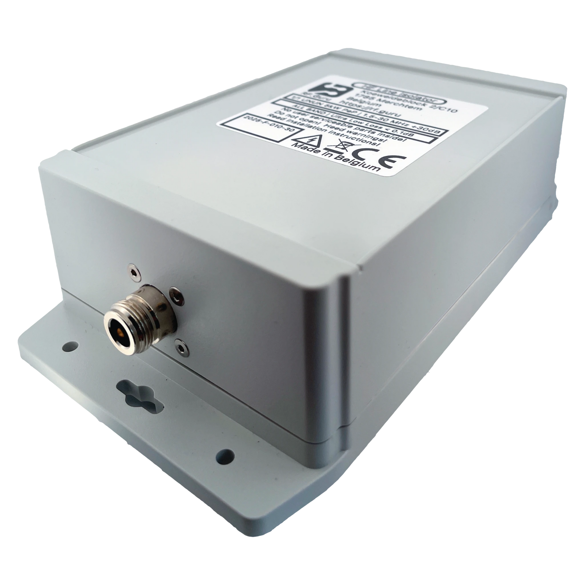
- Connectors: N-type or 7/16 DIN
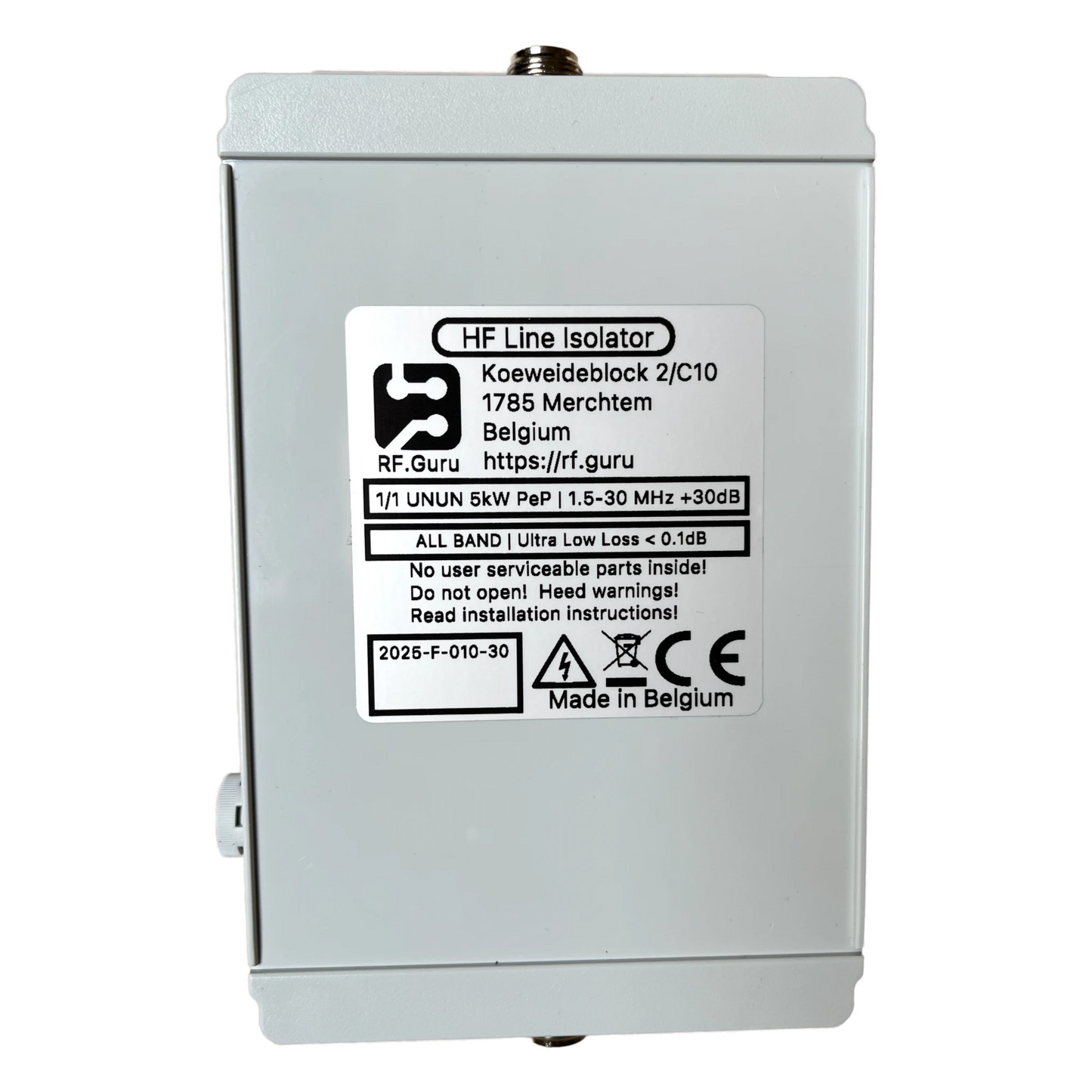
- Enclosure: HV-coated polycarbonate, silicone gaskets, decompression valve
- Reference @ 50 Ω: Vpk ≈ 700 V, Vrms ≈ 500 V, Ipk ≈ 14 A, Irms ≈ 10 A
Measured Performance (Quad-Core, Two Stacks in Series)
Measured per EMC-standard procedure with controlled common-mode current injection and precision sensing under load.
| Band | Choking Impedance (Ω) | Impedance-Equivalent dB (from |Zc|) |
|---|---|---|
| 2 m | 2200 Ω | 33 dB |
| 70 cm | 2400 Ω | 34 dB |
| 23 cm* | 2700 Ω | 35 dB |
| *At 23 cm (1296 MHz), connector and coax heating become the dominant constraint. Apply the explicit 23 cm power derating listed below. Impedance-Equivalent (dB) values are computed directly from measured |ZCM| using a 50 Ω common-mode source reference. Real antennas rarely present 50 Ω in common-mode, so these figures represent the choke’s intrinsic suppression capability, not the attenuation of a real antenna system. More background: Why dB Attenuation Specs on Ham Chokes Are a Mess. | ||
Specifications
- Core configuration: 4 × 2.4″ toroids (two dual stacks in series)
- Connectors: N-type or 7/16 DIN
- Enclosure: HV-coated polycarbonate, silicone gaskets, decompression valve
- Reference @ 50 Ω: Vpk ≈ 700 V, Vrms ≈ 500 V, Ipk ≈ 14 A, Irms ≈ 10 A
- SWR on 2 m VHF: < 1.10
- SWR on 70 cm UHF: < 1.3
-
SWR on 23 cm UHF: < 6 (only usable for RX applications)
Maximum ICAS/CCS Power Ratings (N and 7/16 DIN)
At 23 cm (1296 MHz), apply additional derating due to frequency-dependent loss and thermal rise under mismatch.
| Band | Max ICAS (N / 7/16 DIN) | Max CCS (N / 7/16 DIN) | Notes |
|---|---|---|---|
| 2 m (144 MHz) | ≈ 1 kW ICAS | ≈ 0.5 kW CCS | Assumes low VSWR, quality connector, correct assembly, and reasonable airflow |
| 70 cm (432 MHz) | ≈ 1 kW ICAS | ≈ 0.4 kW CCS | More heating than 2 m — keep VSWR tight |
| 23 cm (1296 MHz) | ≈ 0.5 kW ICAS | ≈ 0.2 kW CCS | Explicit derating at 23 cm due to frequency-dependent loss/heating margins |
Installation Guidance
- Install at the amplifier output, station entry, or antenna feedpoint for maximum suppression.
- Follow the antenna direction marking on the enclosure — orientation matters for section ordering.
- Horizontal or vertical mounting — the enclosure is sealed and pressure-equalized.
- All ratings reflect conservative real-world measurements under continuous carrier load.
At RF.Guru Lab, all baluns are evaluated using EMC-standard dual-probe common-mode testing. One probe injects controlled common-mode current into the device under test, while a second probe measures the resulting CM current at the output.
This method reveals the choke’s true Common-Mode Rejection (CMR) under load — not the differential-mode artifacts seen in simple S21 shield-to-shield VNA tests.
Typical VNA fixtures excite the feedline in differential mode, so they do not measure actual CM behaviour. Our EMC method measures real suppression performance under power, matching what happens in real stations.
Mini-FAQ
-
Q: Why list N and 7/16 DIN together?
— Both are robust, repeatable high-power connectors. For this product class we use the same ICAS/CCS ratings, with explicit derating at 23 cm. -
Q: Why does 23 cm need derating?
— Connector and coax losses rise with frequency, so average-power heating limits drop fast at 1296 MHz. -
Q: Does orientation really matter?
— Yes. The enclosure is marked for antenna direction because internal section ordering can affect suppression and noise blocking performance. -
Q: Best installation point?
— Amplifier output, station entry, or antenna feedpoint. -
Q: Are these values theoretical?
— No. All values are measured under load using EMC-standard common-mode probes.
Interested in more technical content? Subscribe to our updates for deep-dive RF articles and lab notes.
Questions or experiences to share? Contact RF.Guru.
Share