RF Guru
PowerPole Power Supply HAT for Raspberry Pi Zero (12-24V)
PowerPole Power Supply HAT for Raspberry Pi Zero (12-24V)
Regular price
€59,00 EUR
Regular price
Sale price
€59,00 EUR
Unit price
per
Tax included.
Couldn't load pickup availability
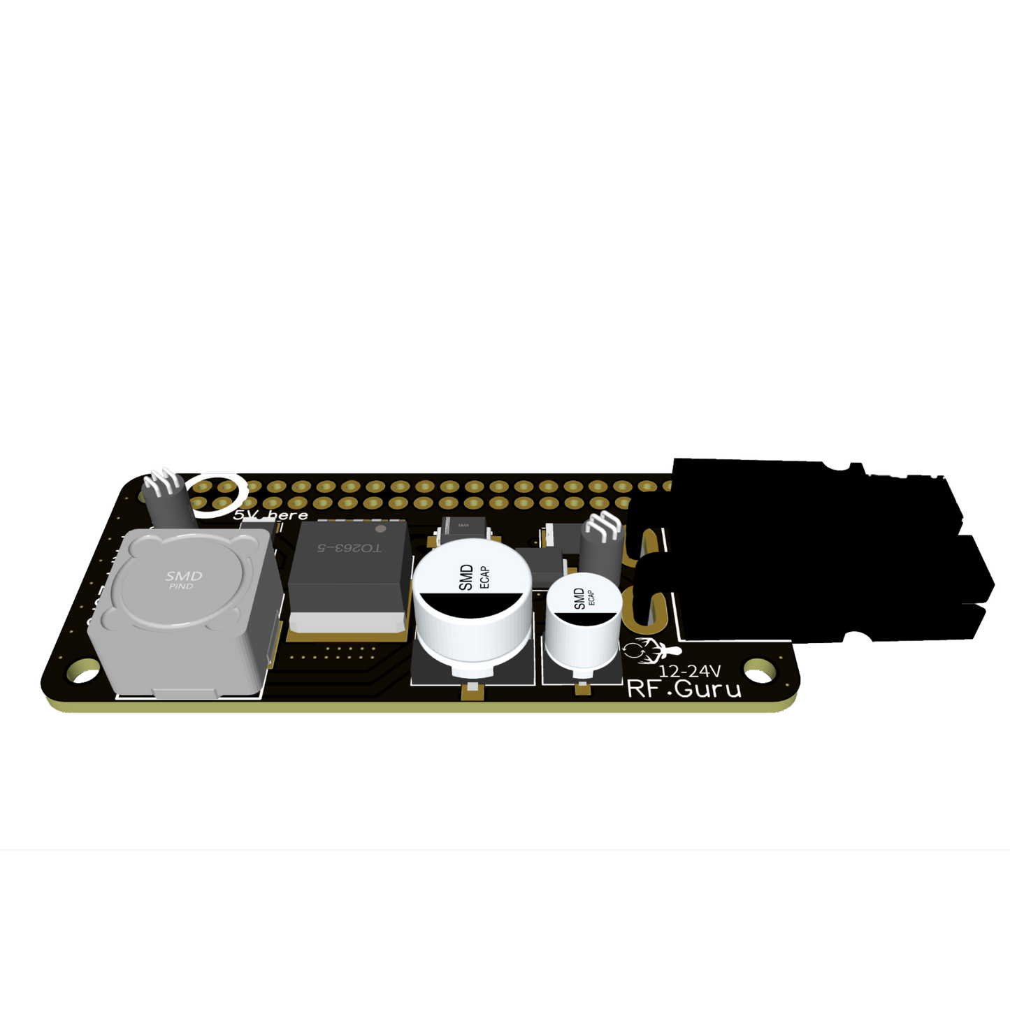
PowerPole Power Supply HAT for Raspberry Pi Zero
Technical Overview: This PowerPole Power Supply HAT is the general-purpose version for Raspberry Pi Zero. It delivers stable ±5V/3A output from a 12–24V input, with ripple kept under 15 mVpp. Unlike the RF-optimized version with downward-facing components, this variant has components facing upward for standard stacking convenience, while still maintaining low emissions below 10 dBuV peak.
Key Features
- Low Ripple: Maintains ripple under 15 mVpp even under CPU load.
- Stackable Design: GPIO passthrough allows multiple HATs to be stacked.
- Upward Orientation: Components face up — simpler build, general usage.
- Robust Power Delivery: 12–24 V input, ±5 V output, up to 3 A current.
- RF Performance: Radiated emissions below 10 dBuV peak in 1–500 MHz tests.
Compatibility
Tested with and compatible with:
- Raspberry Pi Zero
- Raspberry Pi Zero W
- Raspberry Pi Zero WH
- Raspberry Pi Zero 2 W
For Raspberry Pi 3, 4, or 5 we recommend the 2023-P-811 board for higher current needs.
Technical Specifications
- PCB Finish: ENIG (Electroless Nickel Immersion Gold).
- Compliance: RoHS compliant.
- Component Orientation: Upward-facing (alternative RF-optimized downward-facing version available).
- Regulator IC: LM2596S switching regulator.
- Ripple: <15 mVpp.
- Input Voltage: 12–24 V.
- Output Voltage: ±5 V.
- Maximum Current: 3 A.
- Radiated Emissions: <10 dBuV peak (1–500 MHz range).
Performance Measurements
Measured at Pi Zero boot and during high CPU load.
Ripple

Radiated Emissions (1–500 MHz)

Raspberry Pi Zero with PowerPole HAT

Related Reading
Explore more about powering and noise mitigation:
• Troubleshooting Man-Made Noise on Hotspot & RF Devices
• PowerPole Supply HAT Install Guide
• Differential Noise from Raspberry Pi & Arduino
• Troubleshooting Man-Made Noise on Hotspot & RF Devices
• PowerPole Supply HAT Install Guide
• Differential Noise from Raspberry Pi & Arduino