RF Guru
9kW High Power Dual Core 1:1 Balun for Wire Antennas
9kW High Power Dual Core 1:1 Balun for Wire Antennas
Couldn't load pickup availability
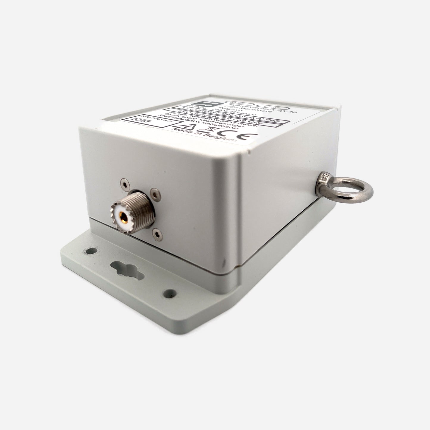
Designed for wire antennas such as dipoles, inverted-V, OCF, and other multiband wire configurations, these high-power current chokes provide stable, high-impedance isolation between the radiating wire and the feedline. They feature a coax input (PL-259, N-type, or 7/16 DIN) and dual INOX M6 terminals for direct wire attachment, plus dual INOX eye bolts for mechanical support. The enclosure is fully sealed and built for permanent outdoor service. All performance values listed below are conservative figures intended to reflect practical operating conditions.
Baluns in a Nutshell
Why “Common-Mode” Is the Most Abused Term in Ham Radio
How Much Choking Do You Really Need — for RX and TX?
Built for the Long Run
Each choke is rated for high-power ICAS duty cycles, tested beyond legal-limit operation. A rugged polycarbonate enclosure with HV coating, silicone gaskets, and a decompression valve ensures long-term reliability under moisture, salt, and UV exposure. Available with PL-259, N-type, or 7/16 DIN input connectors.
Variants
160–40 m Dual-Core Current Choke (9 kW ICAS)
Optimized for low-band wire antennas (160–40 m). All values are conservative, verified under load.
| Band | Choking Impedance (Ω) | Impedance-Equivalent dB (from |Zc|) |
|---|---|---|
| 160 m | 3.5 kΩ | 42.9 dB |
| 80 m | 7.0 kΩ | 48.9 dB |
| 40 m | 8.0 kΩ | 50.1 dB |
|
Approx. 5.0 kΩ → 44.0 dB on 30 m for this choke alone.
In series with the 40–15 m choke (≈ 3.8 kΩ / 43.6 dB) gives ≈ 8.8 kΩ / 50.9 dB total. *Impedance-Equivalent (dB) values are computed directly from |ZCM| using a 50 Ω common-mode source reference. Real antennas rarely present 50 Ω in common-mode, so these dB values represent the choke’s intrinsic suppression capability — not the behavior you would see under a specific antenna load. More: Why dB Attenuation Specs on Ham Chokes Are a Mess.* |
||
40–15 m Dual-Core Current Choke (5 kW ICAS)
Broad HF isolation suitable for EFHW, dipoles, OCF antennas, fan dipoles, and multiband wire operation from 40 through 15 meters. All values are conservative and intended to reflect practical operating conditions.
| Band | Choking Impedance (Ω) | Impedance-Equivalent dB (from |Zc|) |
|---|---|---|
| 40 m | 3.3 kΩ | 42.4 dB |
| 30 m | 3.8 kΩ | 43.6 dB |
| 20 m | 4.3 kΩ | 44.7 dB |
| 17 m | 4.8 kΩ | 45.7 dB |
| 15 m | 5.1 kΩ | 46.2 dB |
| *Impedance-Equivalent (dB) values derived directly from |ZCM| using a 50 Ω CM source reference. They show the choke’s intrinsic suppression, not the CM impedance of a real antenna system.* | ||
15–6 m Dual-Core Current Choke (2 kW ICAS)
High-band HF/VHF isolation suitable for dipoles, fan dipoles, loops, and other wire-fed antenna systems operating from 15 through 6 meters. All values are conservative and intended to reflect practical operating conditions.
| Band | Choking Impedance (Ω) | Impedance-Equivalent dB (from |Zc|) |
|---|---|---|
| 15 m | ≈ 0.85 kΩ | ≈ 30.6 dB |
| 12 m | ≈ 1.1 kΩ | ≈ 32.9 dB |
| 10 m | ≈ 1.25 kΩ | ≈ 34.0 dB |
| 6 m (50–54 MHz) | ≈ 1.5 kΩ | ≈ 35.6 dB |
| *Impedance-Equivalent (dB) values derived directly from |ZCM| using a 50 Ω CM source reference. They show the choke’s intrinsic suppression, not the CM impedance of a real antenna system.* | ||
Maximum ICAS/CCS Power Ratings
| Connector Type | 160–40 m | 40–15 m | 15–6 m | Limiting Factor |
|---|---|---|---|---|
| PL-259 / UHF | ≈2.7 kW | ≈1.3 kW | ≈0.6 kW | Connector |
| N-Type | ≈10 kW | ≈5 kW | ≈2 kW | Coax |
| 7/16 DIN | ≈10 kW | ≈5 kW | ≈2 kW | Coax |
Construction Highlights
- Dual-core structure for thermal & magnetic overhead
- HV internal coating for corona resistance
- IP-rated polycarbonate enclosure
- Pressure-equalizing decompression valve
- Coax input: PL-259, N-type, or 7/16 DIN
- Dual M6 stainless output terminals
- Two INOX 316 eye bolts for strain relief
- All values stated are conservative
At RF.Guru Lab, all current chokes are evaluated using EMC-standard dual-probe common-mode testing. One probe injects controlled CM current; another probe measures the CM current at the output.
This yields true Common-Mode Rejection (CMR) curves based on actual current reduction — not differential-mode VNA S21 plots.
Most VNA tests stimulate the coax in differential mode, not common-mode. Our EMC method measures real CM suppression under load, matching dipole, EFHW, and inverted-V installations.
Mini-FAQ
-
Q: Can I use the 160–40 m choke on upper-HF?
— Yes, but |Zc| drops above 30 m. Pair it with the 40–15 m choke for broader HF coverage above the low bands, and add the 15–6 m version when 12, 10, or 6 m coverage is needed. -
Q: Weatherproof?
— Fully sealed, HV-coated, and pressure-equalized. -
Q: Connection scheme?
— Coax input (PL-259, N-type, or 7/16 DIN), dual M6 wire terminals, dual eye bolts for support. -
Q: Power rating?
— 9 kW ICAS (low-band choke), 5 kW ICAS (40–15 m choke), and 2 kW ICAS (15–6 m choke). -
Q: Measurement accuracy?
— All values are conservative and intended to reflect practical operating conditions.
Interested in more technical content? Subscribe to our updates.
Questions or experiences to share? Contact RF.Guru.
Share