RF Guru
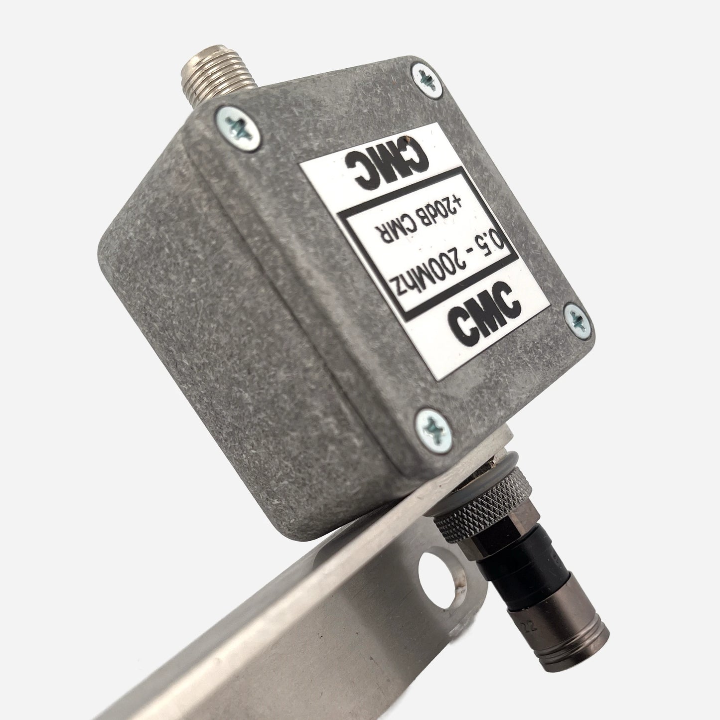
RX 75Ω Line Isolator +30 dB CMR (500 kHz – 200 MHz)
RX 75Ω Line Isolator +30 dB CMR (500 kHz – 200 MHz)
Couldn't load pickup availability
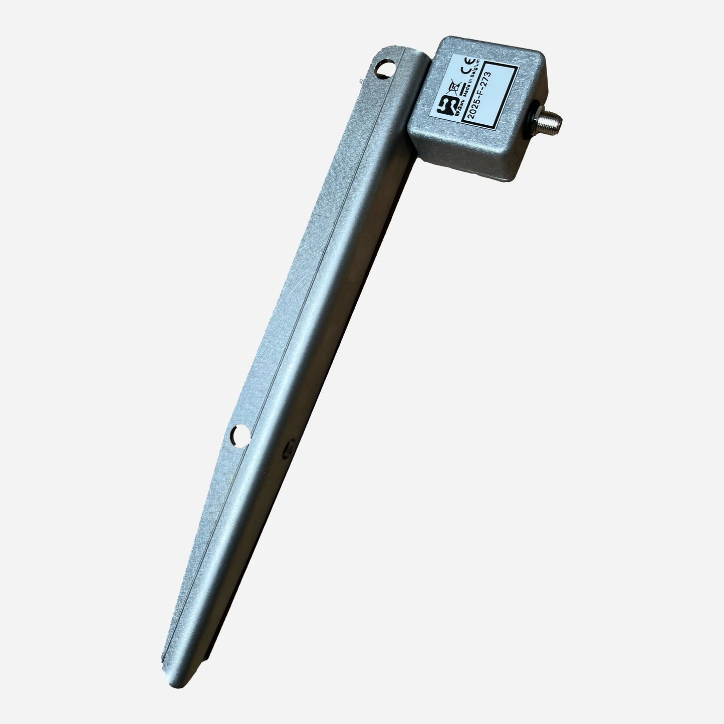
This inline 75 Ω RX choke + surge suppressor integrates a dual-GDT protection network and precision SMD common-mode inductor on a multilayer PCB. Designed for SDRs, active antennas, H-field probes, LoG antennas, and all RX-only systems, it provides wideband isolation and surge protection. The side with the grounded RVS peg must always be pointed away from the antenna — the choke acts in front of the grounded section. The far-side F-connector is DC-isolated using a nylon insert to prevent galvanic path formation.
Baluns in a Nutshell
Why “Common-Mode” Is the Most Abused Term in Ham Radio
How Much Choking Do You Really Need — for RX and TX?
Built for the Long Run
The internal PCB is HV-coated for moisture and insulation stability; the aluminum housing provides mechanical shielding and excellent heat dissipation. Only the connector side is intentionally bonded to the housing — the rest is floating to maintain balance. The two-stage GDT network diverts surges safely without affecting RF.
Installation Strategy
Deploy in a three-stage layout for maximum suppression:
- 1) 25–50 cm after the antenna feedpoint
- 2) Mid-feedline (peg → shack)
- 3) Before shack entry
When chokes are installed in series, their impedances add; each doubling of |ZCM| yields ≈ +6 dB of intrinsic suppression.
Maintenance & Corrosion Care
Apply a small amount of aluminum paste annually where the RVS ground peg contacts the housing.
Measured Common-Mode Performance (75 Ω System)
Conservative values measured using our EMC-standard dual-probe CM method.
| Band | Frequency | Choking |Z| (Ω) | Impedance-Equivalent dB (from |Zc|, 75 Ω ref) |
|---|---|---|---|
| 160 m | 1.9 MHz | ≈ 12 kΩ | 44.1 dB |
| 80 m | 3.5 MHz | ≈ 8 kΩ | 40.6 dB |
| 40 m | 7.0 MHz | ≈ 5 kΩ | 36.6 dB |
| 20 m | 14.2 MHz | ≈ 3 kΩ | 32.3 dB |
| 15 m | 21.2 MHz | ≈ 2 kΩ | 28.8 dB |
| 10 m | 28.4 MHz | ≈ 1.5 kΩ | 26.4 dB |
| *Impedance-Equivalent (dB) values are computed directly from measured |ZCM| using a 75 Ω common-mode reference. These values represent the choke’s intrinsic suppression capability — real antennas rarely present exactly 75 Ω CM (exceptions: active RX antennas). More background: Why dB Attenuation Specs on Ham Chokes Are a Mess.* | |||
| All testing performed with 75 Ω F-connectors, dual-GDT protection, and internal SMD choke. | |||
Construction Highlights
- Aluminum housing (mechanical + RF shielding)
- PCB fully HV-coated
- Dual-GDT surge suppressor
- RVS ground peg for direct earthing
- Opposite F-connector is galvanically isolated
- Optional external choking capacitor supported
- All figures are conservative and verified under load
At RF.Guru Lab we use EMC-standard dual-probe common-mode testing. One probe injects controlled CM current; a second probe measures the CM current at the output.
This yields true Common-Mode Rejection (CMR) — actual RF suppression — not differential-mode S-parameter artifacts.
Typical VNA shield-to-shield sweeps excite the feedline in differential mode. Our method directly measures real CM suppression under load, precisely matching RX installations and active-antenna systems.
Mini-FAQ
-
Q: TX capable?
— No. RX-only. -
Q: Weatherproof?
— Yes, fully sealed and pressure-equalized. -
Q: Where to install?
— Antenna → mid-line → shack. -
Q: Ground peg?
— Always bond the peg to earth. -
Q: Maintenance?
— Apply a small amount of aluminum paste yearly.
Interested in more technical content? Subscribe to our updates.
Questions or experiences to share? Contact RF.Guru.
Share