RF Guru
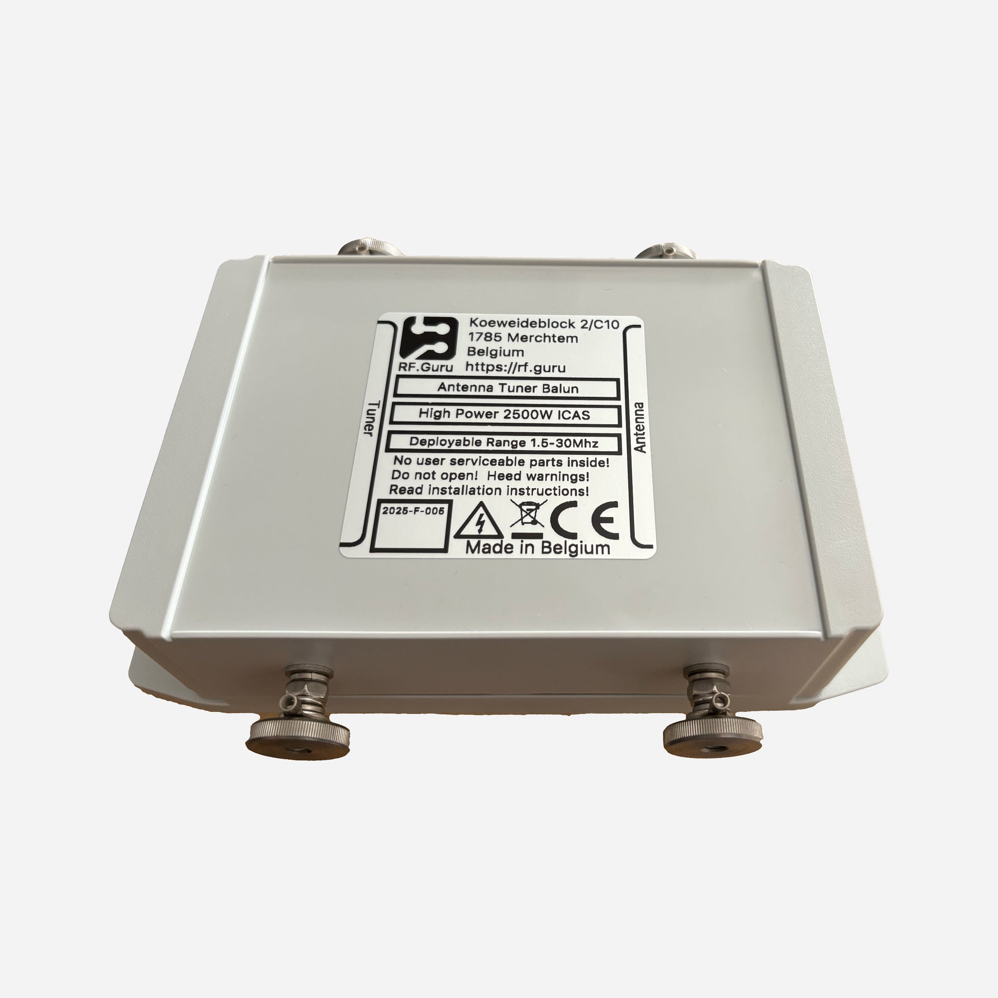
3kW ICAS Quad Core 30-10M High Power 1:1 Antenna Tuner Current Balun
3kW ICAS Quad Core 30-10M High Power 1:1 Antenna Tuner Current Balun
Couldn't load pickup availability
This is the quad-core compact QRO version of our Antenna Tuner series — designed for heavy-duty HF use with four stacked 2.4″ toroids arranged as two dual-core sections in series. It offers outstanding wideband suppression, low insertion loss, and robust QRO power handling for amplifier outputs and antenna feedpoints. Encased in a HV-coated polycarbonate enclosure with silicone gaskets and a decompression valve, it is built for long-term outdoor operation. All data are measured under load — no simulations.
Baluns in a Nutshell
Why “Common-Mode” Is the Most Abused Term in Ham Radio
How Much Choking Do You Really Need — for RX and TX?
Purpose-Built for Heavy-Duty HF Service
This quad-core assembly provides exceptional wideband suppression and generous thermal overhead. Ideal at amplifier outputs, station entry points, or antenna feedpoints to maximize system isolation across the 30–10 m spectrum.
Specifications
- Core configuration: 4 × 2.4″ toroids (two dual-core stacks in series)
- Winding: 4 turns of high-temperature coax per section
- Terminals: 4 × M6 INOX 316 bolts with Teflon spacers
- Enclosure: HV-coated polycarbonate, silicone gaskets, decompression valve
- Power rating: 3 kW ICAS / 1.2 kW CCS
- Reference @ 50 Ω: Vpk ≈ 700 V, Vrms ≈ 500 V, Ipk ≈ 14 A, Irms ≈ 10 A
Measured Performance (Quad-Core, Two Stacks in Series)
Measured using EMC-standard current injection with precision CM sensing under load.
| Band | Choking Impedance (Ω) | Impedance-Equivalent dB (from |Zc|) |
|---|---|---|
| 30 m | 14.21 kΩ | 55.1 dB |
| 20 m | 16.63 kΩ | 56.5 dB |
| 17 m | 6.39 kΩ | 48.2 dB |
| 15 m | 4.51 kΩ | 45.1 dB |
| 12 m | 3.35 kΩ | 42.6 dB |
| 10 m | 2.73 kΩ | 40.8 dB |
| *Impedance-Equivalent (dB) values are derived directly from measured |ZCM| using a 50 Ω common-mode source reference. Real antennas seldom present 50 Ω CM, so these dB values express the choke’s intrinsic suppression capability — not the attenuation observed under a specific antenna load. More details: Why dB Attenuation Specs on Ham Chokes Are a Mess.* | ||
Excellent wideband intrinsic suppression from 30–10 m. For extended low-band coverage, cascade with a 160–40 m choke.
Installation Guidance
- Install at amplifier output, station entry, or antenna feedpoint.
- Mount horizontally or vertically — enclosure is sealed and pressure-equalized.
- All values represent conservative real-world measurements under CCS/ICAS load.
All RF.Guru chokes are evaluated using the EMC common-mode method with dual probes — one injects calibrated CM current onto the outer conductor, the other measures residual CM current. This yields true Common-Mode Rejection (CMR) data, representing actual shield suppression under load.
Differential VNA sweeps do not measure CM behavior. The EMC method captures the real CM suppression your coax and tuner system will experience.
Mini-FAQ
-
Q: What makes this a quad-core choke?
— Two dual-core stacks in series, doubling |Zc| and thermal capacity. -
Q: Can it replace two separate units?
— Yes — equivalent to two dual-core chokes in series for upper HF. -
Q: What power levels?
— About 3 kW ICAS (PL). Higher with N-type connectors. -
Q: Installation point?
— Amplifier output, station entry, or feedpoint. -
Q: Are the figures theoretical?
— No — all values measured with calibrated EMC CM probes.
Interested in more technical content? Subscribe to our updates.
Questions or experiences to share? Contact RF.Guru.
Share

