RF Guru
5kW ICAS High Power Dual Core 1:1 Current Balun For Spiderbeam®
5kW ICAS High Power Dual Core 1:1 Current Balun For Spiderbeam®
Couldn't load pickup availability
Please allow 2–3 weeks for your order to be completed and shipped.
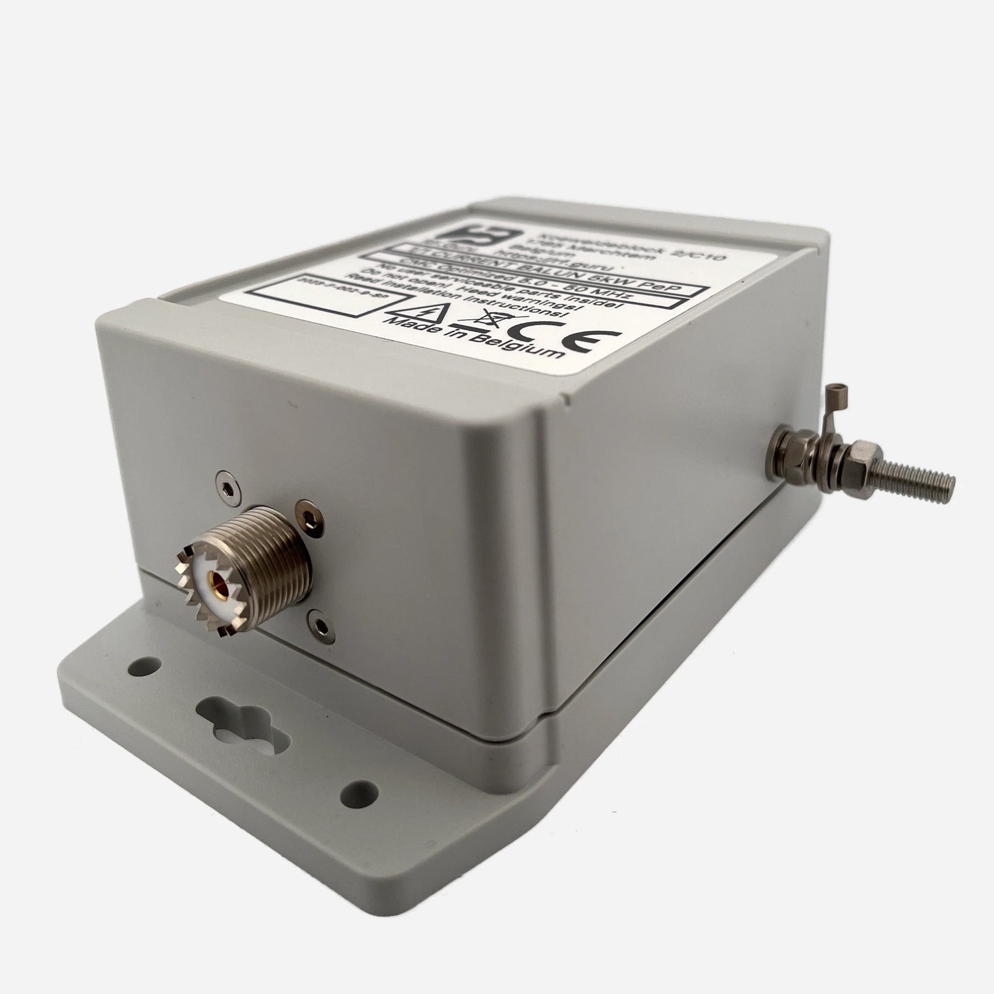
Purpose-built for SpiderBeam 5-Band Yagis and similar multiband beams, this 30–10 m dual-core current choke provides wideband isolation across the upper-HF bands — including 6 m. It eliminates feedline-induced RF that distorts patterns, shifts SWR, or raises the shack noise floor. Housed in a rugged polycarbonate HV-coated enclosure with silicone gaskets and a decompression valve, it is designed for permanent outdoor installation. All listed performance values are conservative, measured under real-world loads.
Baluns in a Nutshell
Why “Common-Mode” Is the Most Abused Term in Ham Radio
How Much Choking Do You Really Need — for RX and TX?
Optimized for SpiderBeam Systems
Mounted at the feedpoint or boom balun junction, this choke ensures proper current balance across all five SpiderBeam bands (20 / 17 / 15 / 12 / 10 m). It suppresses common-mode currents flowing on the coax shield. Available with PL-259 or N-type connectors.
30–10 m Dual-Core Current Choke (9 kW ICAS)
Broad upper-HF suppression with robust outdoor durability. All impedance and dB values are conservative, verified with calibrated CM injection.
| Band | Choking Impedance (Ω) | Impedance-Equivalent dB (from |Zc|) |
|---|---|---|
| 30 m | 3.0 kΩ | 41.6 dB |
| 20 m | 2.5 kΩ | 40.0 dB |
| 17 m | 2.3 kΩ | 39.3 dB |
| 15 m | 2.1 kΩ | 38.5 dB |
| 12 m | 1.9 kΩ | 37.6 dB |
| 10 m | 1.7 kΩ | 36.7 dB |
| *Impedance-Equivalent (dB) values are computed directly from measured |ZCM| using a 50 Ω common-mode source reference. Real antennas rarely present 50 Ω in common-mode, so these dB values represent the choke’s intrinsic suppression capability — not the attenuation you would see in a specific antenna installation. More background: Why dB Attenuation Specs on Ham Chokes Are a Mess.* | ||
Maximum ICAS/CCS Power Ratings
| Connector Type | 160–40 m Band | 30–10 m Band | 6–2 m Band | Limiting Factor |
|---|---|---|---|---|
| PL-259 / UHF | ≈ 2.7 kW ICAS | ≈ 1.3 kW ICAS | ≈ 0.6 kW ICAS | Connector |
| Type-N | ≈ 10 kW ICAS | ≈ 5 kW ICAS | ≈ 2 kW ICAS | Coax |
| 7/16 DIN | ≈ 10 kW ICAS | ≈ 5 kW ICAS | ≈ 2 kW ICAS | Coax |
Construction Highlights
- Dual-core ferrite stack for high magnetic & thermal overhead
- HV-coated internal winding to prevent corona
- UV-resistant polycarbonate housing with silicone gaskets
- Integrated decompression valve
- Connector options: PL-259 or Type-N
- All figures are conservative and measured under load
All RF.Guru chokes are measured using EMC-grade dual-probe common-mode testing. One probe injects controlled CM current, while the second probe measures the CM current leaving the choke.
This yields a true Common-Mode Rejection (CMR) curve based on actual CM current reduction — not differential-mode VNAs.
Typical VNA sweeps excite the coax in differential mode and do not measure common-mode behaviour. Our EMC method measures real CM suppression under load, matching beam and vertical installations.
Mini-FAQ
-
Q: Is this choke made for SpiderBeam antennas?
— Yes. It covers all SpiderBeam HF bands (20–10 m) with wideband suppression. -
Q: Best installation location?
— At the feedpoint or balun junction to stop shield current before it enters the boom/mast. -
Q: Connector options?
— PL-259 or Type-N. -
Q: Outdoor rated?
— Absolutely — sealed, coated, and pressure-equalized. -
Q: Can it handle legal limit?
— Yes, rated to 9 kW ICAS.
Interested in more technical content? Subscribe to our updates.
Questions or experiences to share? Contact RF.Guru.
Share