RF Guru
9kW ICAS High-Power Dual-Core Band Specific 1:1 Current Balun or Choke
9kW ICAS High-Power Dual-Core Band Specific 1:1 Current Balun or Choke
Couldn't load pickup availability
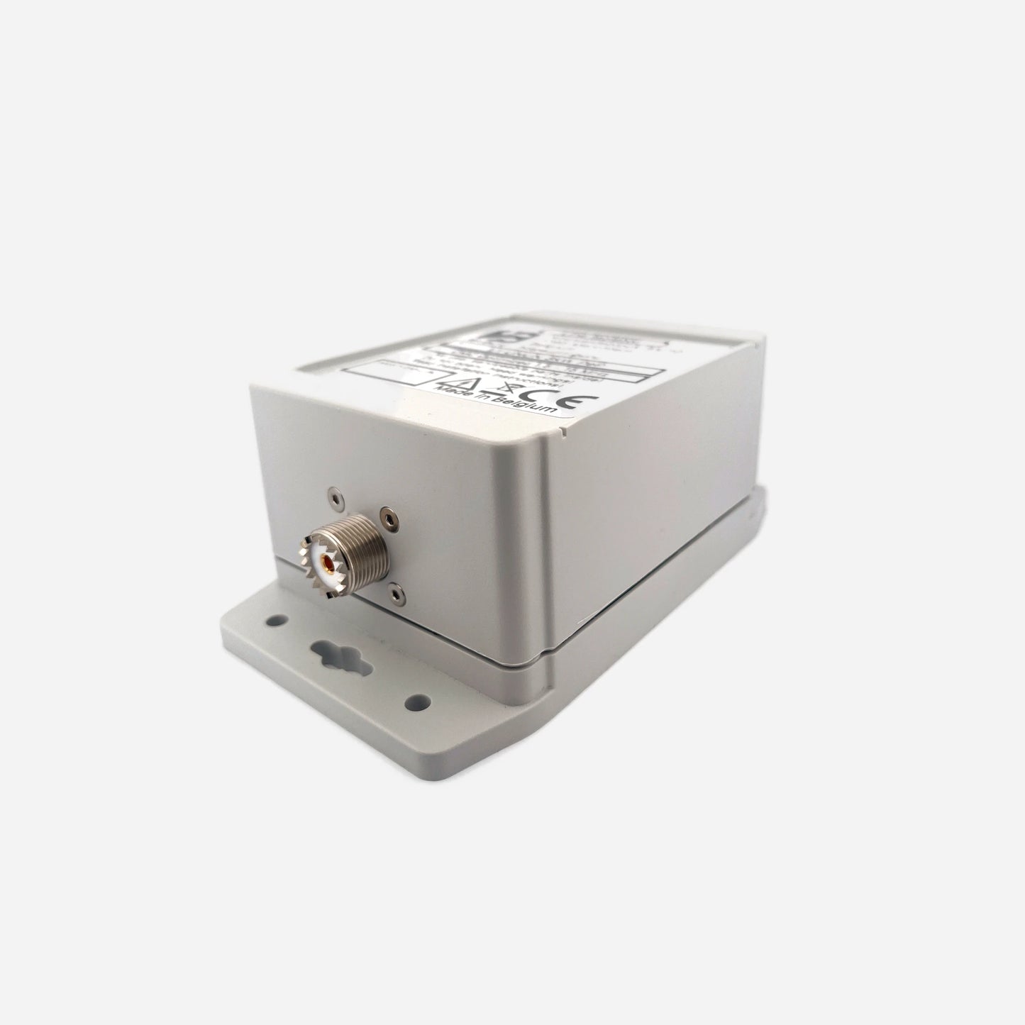
Engineered for serious HF/VHF operators, these high-power current chokes are built on stacked dual-core architecture inside a rugged polycarbonate enclosure with HV coating, custom gaskets, and a decompression valve for outdoor QRO use. Each choke is hand-assembled and verified for proper impedance across its specified range. All performance values listed below are conservative figures intended to reflect practical operating conditions.
Baluns in a Nutshell
Why “Common-Mode” Is the Most Abused Term in Ham Radio
How Much Choking Do You Really Need — for RX and TX?
Built for the Long Run
Each model is designed for high-power ICAS duty cycles, tested to withstand sustained legal-limit operation and beyond. The fully sealed build resists moisture, salt, and UV exposure, while the internal HV coating prevents corona discharge and maintains stable impedance under high voltage stress. Available with PL-259, N-type, or 7/16 DIN connectors for maximum compatibility with your station’s feedline system.
Variants
160–40 m Dual-Core Current Choke (9 kW ICAS)
Optimized for the low bands, offering deep suppression of common-mode currents on 160, 80, and 40 meters. If extended operation on 30 m is needed, the 40–15 m choke can be placed in series. Supplied with your choice of PL-259, N-type, or 7/16 DIN connectors. Impedance values are conservative and verified under real QRO load conditions.
| Band | Choking Impedance (Ω) | Impedance-Equivalent dB (from |Zc|) |
|---|---|---|
| 160 m | 3.5 kΩ | 42.9 dB |
| 80 m | 7.0 kΩ | 48.9 dB |
| 40 m | 8.0 kΩ | 50.1 dB |
|
Approx. 5.0 kΩ → 44.0 dB on 30 m for this choke alone. In series with the 40–15 m choke (≈ 3.8 kΩ / 43.6 dB on 30 m) gives ≈ 8.8 kΩ / 50.9 dB total. *Impedance-Equivalent (dB) values are computed directly from measured |ZCM| using a 50 Ω common-mode source reference. Real antennas seldom present 50 Ω in common-mode, so these numbers represent the choke’s intrinsic suppression capability, not the attenuation you would see under a specific antenna load. Full explanation: Why dB Attenuation Specs on Ham Chokes Are a Mess. |
||
40–15 m Dual-Core Current Choke (5 kW ICAS)
Broad HF design providing consistent isolation from 40 through 15 meters. Ideal as a feedline choke for multiband verticals, Yagis, or EFHWs operating across the main HF contest and DX bands. Available with PL-259, N-type, or 7/16 DIN connectors. All impedance and dB figures are conservative and intended to reflect practical operating conditions.
| Band | Choking Impedance (Ω) | Impedance-Equivalent dB (from |Zc|) |
|---|---|---|
| 40 m | 3.3 kΩ | 42.4 dB |
| 30 m | 3.8 kΩ | 43.6 dB |
| 20 m | 4.3 kΩ | 44.7 dB |
| 17 m | 4.8 kΩ | 45.7 dB |
| 15 m | 5.1 kΩ | 46.2 dB |
|
*Impedance-Equivalent (dB) values are computed from conservative |ZCM| values using a 50 Ω common-mode source reference. Because real antennas rarely present a 50 Ω common-mode impedance, these values represent the choke’s intrinsic suppression capability, not the attenuation that would occur with a specific antenna load. Full details: Why dB Attenuation Specs on Ham Chokes Are a Mess. |
||
When multiple chokes are installed in series, their impedances add, increasing the total common-mode suppression. Each doubling of total choking impedance corresponds to roughly +6 dB of additional intrinsic suppression.
15–6 m Dual-Core Current Choke (2 kW ICAS)
High-band HF/VHF design providing useful common-mode isolation from 15 through 6 meters. Ideal for multiband beams, upper-HF verticals, and 50 MHz installations where feedline current control is still critical. Offered with PL-259, N-type, or 7/16 DIN connectors. All figures are conservative and intended to reflect practical operating conditions.
| Band | Choking Impedance (Ω) | Impedance-Equivalent dB (from |Zc|) |
|---|---|---|
| 15 m | ≈ 0.85 kΩ | ≈ 30.6 dB |
| 12 m | ≈ 1.1 kΩ | ≈ 32.9 dB |
| 10 m | ≈ 1.25 kΩ | ≈ 34.0 dB |
| 6 m (50–54 MHz) | ≈ 1.5 kΩ | ≈ 35.6 dB |
|
*Impedance-Equivalent (dB) values for upper-HF and VHF use the same method: |ZCM| converted on a 50 Ω common-mode reference. This ensures consistent comparison across products but does not imply that an antenna presents 50 Ω in common-mode. These values express the choke’s inherent ability to impede shield current, not the attenuation produced in a particular antenna installation. More explanation: Why dB Attenuation Specs on Ham Chokes Are a Mess. |
||
Maximum ICAS/CCS Power Ratings
| Connector Type | 160–40 m Band | 40–15 m Band | 15–6 m Band | Limiting Factor |
|---|---|---|---|---|
| PL-259 / UHF | ≈ 2.7 kW ICAS | ≈ 1.3 kW ICAS | ≈ 0.6 kW ICAS | Connector |
| Type-N | ≈ 10 kW ICAS | ≈ 5 kW ICAS | ≈ 2 kW ICAS | Coax |
| 7/16 DIN | ≈ 10 kW ICAS | ≈ 5 kW ICAS | ≈ 2 kW ICAS | Coax |
Construction Highlights
- Dual-core architecture for extended thermal and magnetic headroom
- High-voltage internal coating to prevent corona and arcing
- Polycarbonate housing with precision-cut silicone gaskets for IP-rated sealing
- Integrated decompression valve for pressure equalization
- Connector options: PL-259, N-type, or 7/16 DIN (field-serviceable)
- All impedance and dB values stated are conservative
At RF.Guru Lab, all current chokes are evaluated using EMC-standard dual-probe common-mode testing. One probe injects controlled common-mode current into the device under test, while a second probe measures the resulting CM current at the output.
This method reveals the choke’s true common-mode suppression — including behavior under high voltage, reactive loads, and realistic coax geometries — without the differential-mode contamination typically seen in simple VNA S21 shield-to-shield tests.
Most VNA fixtures excite the coax in differential mode, not common-mode, and therefore do not measure the behavior that matters on real antennas. Our EMC method measures true CM suppression under load, matching what actually happens on a tuner-fed HF antenna system.
Mini-FAQ
-
Q: Can I use the 160–40 m choke above 30 m?
— You can, but its impedance drops rapidly. Pair it with the 40–15 m choke in series for broader HF suppression above the low bands. -
Q: Are these waterproof for outdoor use?
— Yes. Each enclosure is fully gasket-sealed, HV-coated, and equipped with a decompression valve. -
Q: What connectors are available?
— All variants are offered with PL-259, N-type, or 7/16 DIN connectors, each rated for QRO duty cycles. -
Q: What does 9 kW ICAS mean?
— It refers to Intermittent Commercial and Amateur Service: suitable for high-power contest and amplifier operation. -
Q: How accurate are the impedance numbers?
— They are deliberately conservative and intended to reflect practical operating conditions.
Interested in more technical content? Subscribe to our updates for deep-dive RF articles and lab notes.
Questions or experiences to share? Contact RF.Guru.
Share