RF Guru
9kW ICAS Dual Core 1:1 Balun For Verticals, Beams and Rotary Dipoles
9kW ICAS Dual Core 1:1 Balun For Verticals, Beams and Rotary Dipoles
Couldn't load pickup availability
Please allow 2–3 weeks for your order to be completed and shipped.
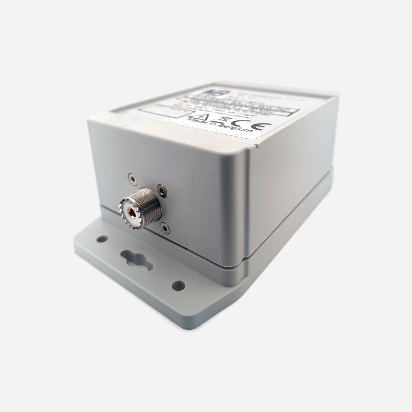
Engineered for rotary dipoles, verticals, and beam antennas, these high-power current chokes suppress feedline-induced RF currents directly at the driven element. Built on a stacked dual-core structure inside a sealed polycarbonate HV-coated enclosure, they include a PL-259, N-type, or 7/16 DIN input and dual INOX M6 terminals for antenna connection. All performance values below are conservative figures intended to reflect practical operating conditions.
Baluns in a Nutshell
Why “Common-Mode” Is the Most Abused Term in Ham Radio
How Much Choking Do You Really Need — for RX and TX?
Built for the Long Run
Designed for ICAS duty cycles and high drive imbalance, these chokes provide stable suppression on high-power beams, rotary dipoles, and vertical arrays. The enclosure is HV coated, gasket sealed, and pressure equalized for long-term reliability.
Variants
160–40 m Rotary-Dipole / Low-Band Beam Choke (9 kW ICAS)
Optimized for 160, 80, and 40 m. All values conservative, verified under QRO load.
| Band | Choking Impedance (Ω) | Impedance-Equivalent dB (from |Zc|) |
|---|---|---|
| 160 m | 3.5 kΩ | 42.9 dB |
| 80 m | 7.0 kΩ | 48.9 dB |
| 40 m | 8.0 kΩ | 50.1 dB |
|
Approx. 5.0 kΩ → 44.0 dB on 30 m alone. In series with the 40–15 m choke (≈ 3.8 kΩ / 43.6 dB on 30 m) gives ≈ 8.8 kΩ / 50.9 dB total. *Impedance-Equivalent (dB) values are derived directly from |ZCM| using a 50 Ω common-mode source reference. Real antennas rarely present 50 Ω CM, so these values represent the choke’s intrinsic suppression capability — not loaded attenuation. See: Why dB Attenuation Specs on Ham Chokes Are a Mess.* |
||
40–15 m Beam / Rotary-Dipole Feed Choke (5 kW ICAS)
Ideal as a boom-mounted or mast-mounted feed choke for monoband and multiband HF Yagis, rotary dipoles, and vertical arrays operating from 40 through 15 meters. All values are conservative and intended to reflect practical operating conditions.
| Band | Choking Impedance (Ω) | Impedance-Equivalent dB (from |Zc|) |
|---|---|---|
| 40 m | 3.3 kΩ | 42.4 dB |
| 30 m | 3.8 kΩ | 43.6 dB |
| 20 m | 4.3 kΩ | 44.7 dB |
| 17 m | 4.8 kΩ | 45.7 dB |
| 15 m | 5.1 kΩ | 46.2 dB |
| *Impedance-Equivalent (dB) values computed from |ZCM| using a 50 Ω common-mode reference. They express the choke’s intrinsic suppression, not the CM impedance of a real beam, dipole, or vertical installation.* | ||
15–6 m High-Band Beam / Rotary-Dipole Choke (2 kW ICAS)
High-band HF/VHF design for 15, 12, 10, and 6 meter beam or rotary-dipole feedpoints. Useful where feedline current control remains critical across the upper HF bands and through 50–54 MHz. All figures are conservative and intended to reflect practical operating conditions.
| Band | Choking Impedance (Ω) | Impedance-Equivalent dB (from |Zc|) |
|---|---|---|
| 15 m | ≈ 0.85 kΩ | ≈ 30.6 dB |
| 12 m | ≈ 1.1 kΩ | ≈ 32.9 dB |
| 10 m | ≈ 1.25 kΩ | ≈ 34.0 dB |
| 6 m (50–54 MHz) | ≈ 1.5 kΩ | ≈ 35.6 dB |
| *Impedance-Equivalent (dB) values derived from |ZCM| on a 50 Ω common-mode reference — representing the choke’s inherent suppression ability, not antenna-specific CM behavior.* | ||
Maximum ICAS/CCS Power Ratings
| Connector Type | 160–40 m | 40–15 m | 15–6 m | Limiting Factor |
|---|---|---|---|---|
| PL-259 / UHF | ≈ 2.7 kW | ≈ 1.3 kW | ≈ 0.6 kW | Connector |
| N-Type | ≈ 10 kW | ≈ 5 kW | ≈ 2 kW | Coax |
| 7/16 DIN | ≈ 10 kW | ≈ 5 kW | ≈ 2 kW | Coax |
Construction Highlights
- Dual-core structure
- PL-259, N-type, or 7/16 DIN input
- Dual M6 stainless balanced outputs
- INOX 316 eye bolts for mechanical support
- HV internal coating
- Polycarbonate enclosure with silicone gaskets
- Decompression valve
- All values stated are conservative
All RF.Guru chokes are tested using EMC-standard dual-probe CM measurement: one probe injects controlled CM current, the second measures CM current at the output.
This produces real Common-Mode Rejection (CMR) data — based on actual current reduction — not differential-mode VNA artifacts.
Typical VNAs excite the coax in differential mode and do not measure common-mode behavior. Our EMC rig measures true CM suppression under load, exactly as it appears on beam, dipole, and vertical installations.
Mini-FAQ
-
Q: Which choke for rotary dipoles?
— For low-band rotary dipoles, the 160–40 m version. For 40 through 15 m feedpoints, the 40–15 m version. -
Q: Best choke for HF Yagis?
— The 40–15 m version. -
Q: Do you have a 15–6 m beam choke?
— Yes, covering 15, 12, 10, and 6 meters. -
Q: Is it weatherproof?
— Fully sealed, HV-coated, and pressure-equalized. -
Q: Connector options?
— PL-259, N-type, or 7/16 DIN input, dual M6 stainless outputs.
Interested in more technical content? Subscribe to our updates.
Questions or experiences to share? Contact RF.Guru.
Share