RF Guru
EchoTracer3 — An active WideBand RX E-Probe — 10 KHz to 1.5 GHz
EchoTracer3 — An active WideBand RX E-Probe — 10 KHz to 1.5 GHz
Couldn't load pickup availability
EchoTracer3: Choose the Receiving System That Fits Your Spectrum
One protected outdoor E-field probe platform, configured with the whip and receiver-side Bias-T that match the frequencies you actually monitor.
Assembly and fulfilment normally take 1–5 weeks, depending on order volume. Contact RF.Guru before ordering when a precise estimate matters.
Order coax and compatible connectors together and RF.Guru will crimp the connectors before shipping at no extra charge.
Coverage is configuration-dependent. EchoTracer3 is not one flat-response 10 kHz–1.5 GHz antenna. The 1 m configurations emphasise LF/HF through VHF; the modular short-whip configuration shifts the practical focus upward. The Bias-T must cover the same frequency range as the selected whip.
Step 1: Choose the Whip
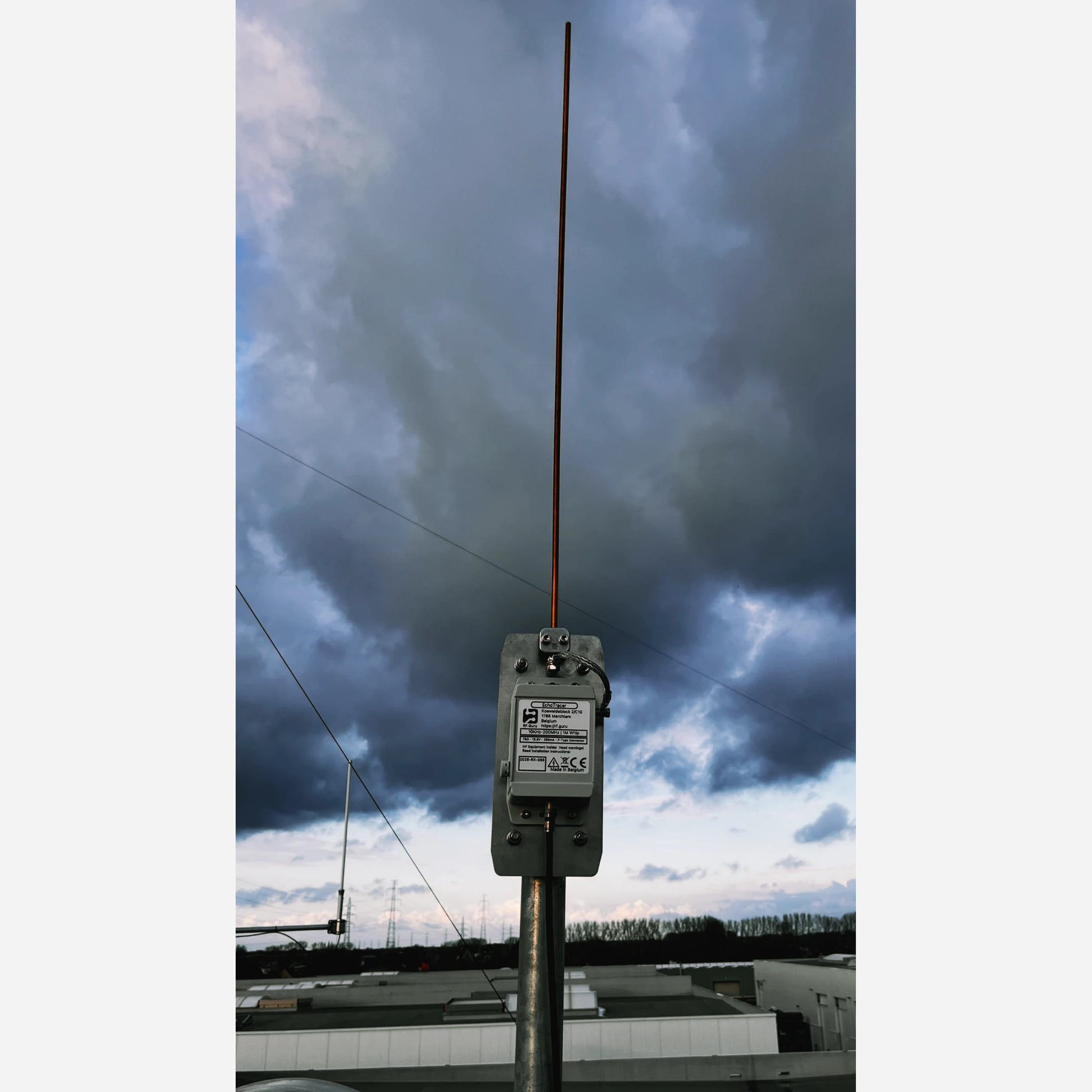
The default choice for the broadest LF/HF emphasis, with a published monitoring guide of approximately 10 kHz–200 MHz.
Choose stainless steel for outdoor durability or brass when conductivity and modularity are the priority. The complete installation matters more than a small material difference.
Use the 25, 50 or 75 cm effective length to move the practical emphasis upward without buying a separate probe for every range.
The published choice for approximately 10 MHz–1.5 GHz monitoring. It intentionally trades away lower-HF coupling.
| Whip setup | Published use range | Best fit |
|---|---|---|
| 1 m stainless steel + capacitive hat | Approximately 10 kHz–200 MHz | VLF/LF/HF emphasis through VHF |
| 75 cm | Below approximately 400 MHz | Broad HF/VHF use with less lower-HF compromise than shorter whips |
| 50 cm | Below approximately 600 MHz | HF/VHF/UHF scanning where lower-HF coupling is less important |
| 25 cm | Approximately 10 MHz–1.5 GHz | VHF/UHF/L-band emphasis, including 1090 MHz monitoring |
Step 2: Choose the Bias-T
The Bias-T is selected separately and is not included. Choose a model whose lower and upper passband limits both contain the spectrum you intend to receive.
| Bias-T | Specified passband | Choose it for | Receiver interface |
|---|---|---|---|
| Bias-T 200 | 10 kHz–200 MHz | VLF/LF/HF through VHF | 75-to-50 Ω resistive matching |
| Bias-T 600 | 500 kHz–600 MHz | LF/HF/VHF/UHF scanning | 75-to-50 Ω transformer |
| Bias-T 1500 | 20 MHz–1.5 GHz | VHF/UHF/L-band | Starts above LF/lower HF |
What Is Included?
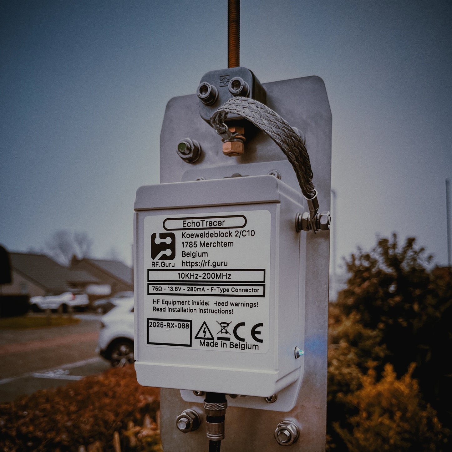
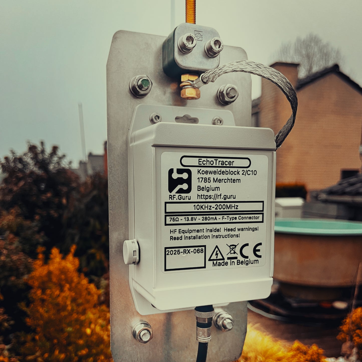
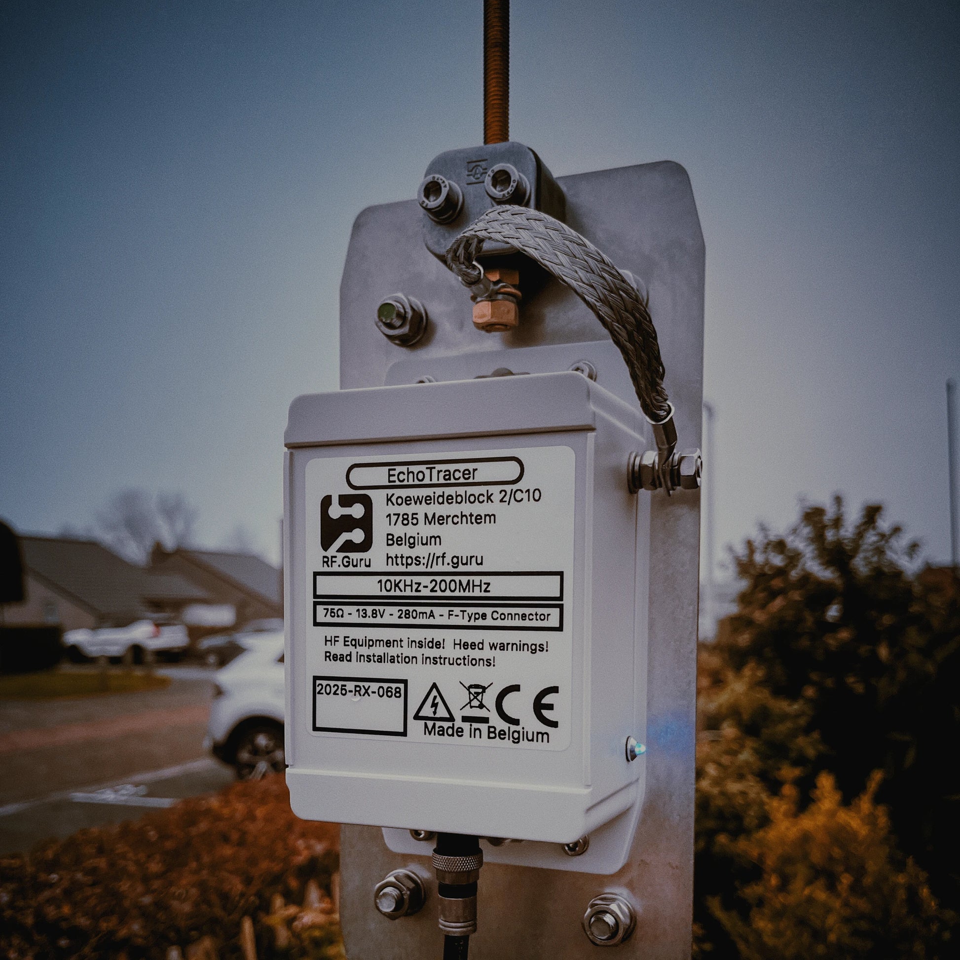
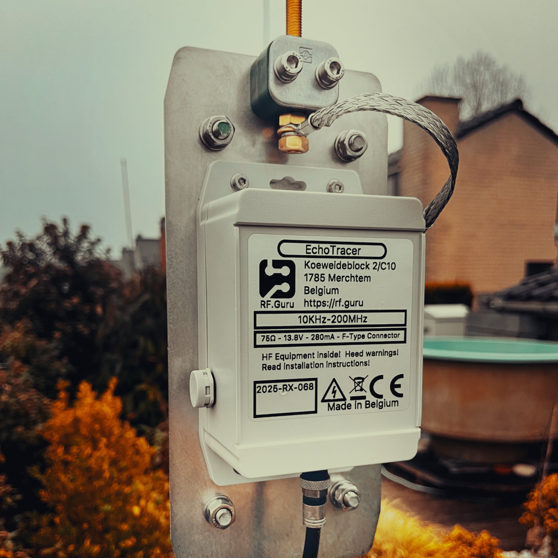
Sealed EchoTracer3 module, stainless-steel mounting plate and the whip configuration selected with the product variant.
Bias-T, receive-line isolators, ground-peg assembly, 75 Ω coax, connectors and any RX Disconnect on TX station interlock are not included.
The Recommended Receive-System Layout
Installation refinement: in a difficult common-mode environment, a second receive-line isolator before shack entry can help. Keep the cable route repeatable and assess wanted-signal SNR—not S-meter level alone—when changing height, bonding or isolation.
Why EchoTracer3 Is an Active Receive System
The whip samples the local electric field. Layered static, ESD and surge limiting improves robustness without presenting the field element as a conventional matched transmitter antenna.
The active path uses selective broadcast-band rejection and frequency-dependent response control to reduce overload and unwanted mixing risk.
Output coupling, common-mode suppression and filtered Bias-T power are designed together so the feedline is controlled as part of the receiving system.
Protection boundary: removing Bias-T power grounds the whip. That is a useful equipment state, but it is not a lightning-protection system and it does not define a universal safe transmitter power or separation. Disconnect outdoor antennas during thunderstorms and integrate earthing, bonding, surge protection and any transmit interlock with the complete station and building design.
Placement and Height
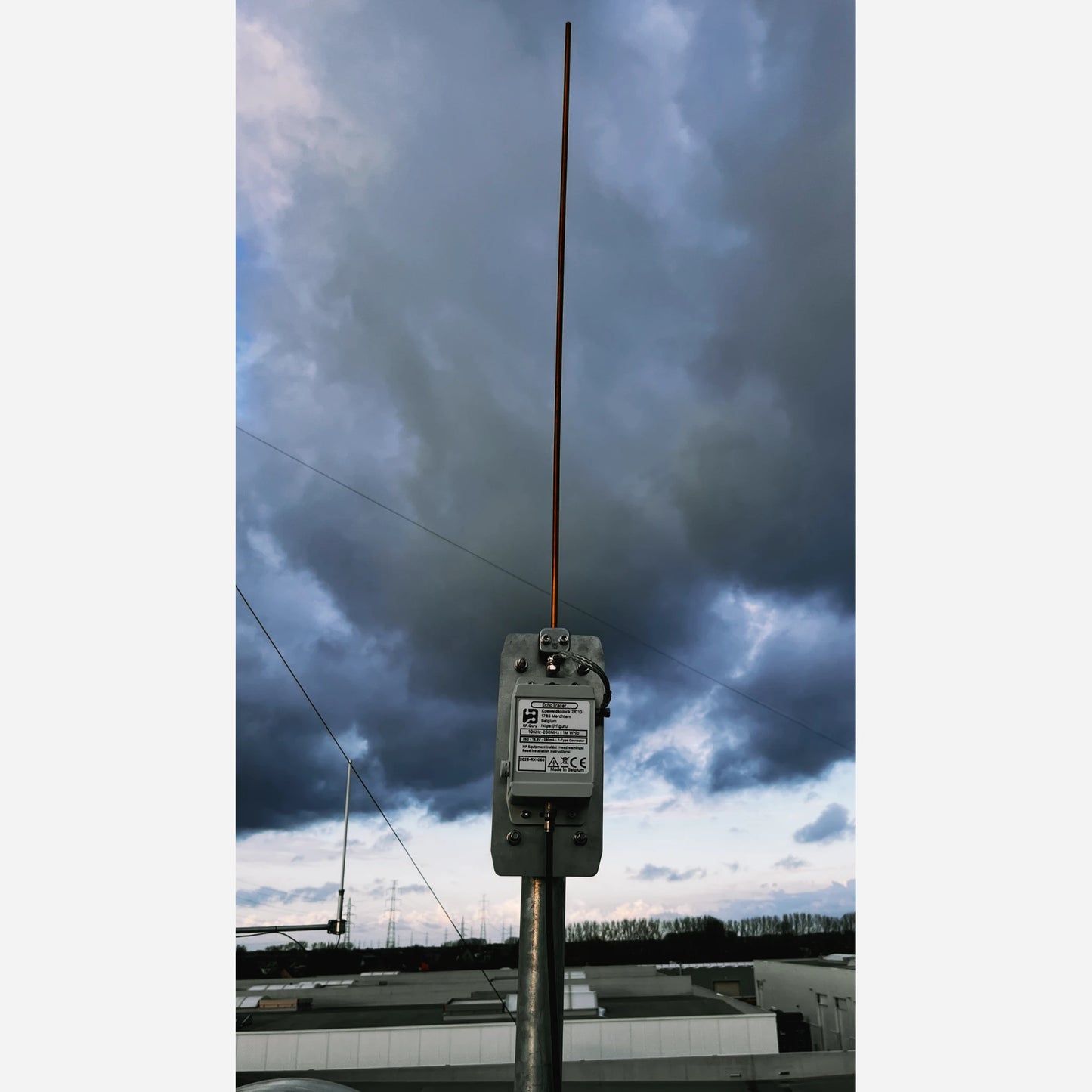
- Use a non-conductive mast and place the probe away from switching supplies, routers, LED drivers, building wiring and other local electric-field noise.
- Use 2–4 m as a practical comparison range, not a maximum or universal optimum. Test more than one height and retain the position that gives the best wanted-signal SNR and overload margin at your site.
- Control nearby conductors. Roofs, gutters, fences, masts and cable routes change capacitance, response and common-mode paths.
- Do not improvise a separate earth electrode. Any mast-base bond, coax entry bond or surge protection must be coordinated with the applicable building earthing and lightning-protection design.
Maintenance
Apply a thin layer of material-compatible anti-corrosion compound to external whip threads and hardware, following the compound and connector manufacturers’ instructions. Keep RF connector mating surfaces clean and dry; do not put grease inside the coax connector. Inspect the enclosure, whip joint, cable strain relief, weather sealing and bonds as part of normal outdoor maintenance.
Technical Specifications
| Parameter | Product-level specification |
|---|---|
| Function | Receive-only active vertical E-field probe |
| Coverage | Approximately 10 kHz–1.5 GHz across different whip and Bias-T configurations |
| HF-focused setup | 1 m stainless-steel whip with capacitive hat, approximately 10 kHz–200 MHz |
| Output | Isolated 75 Ω F-type receive interface with common-mode suppression |
| Broadcast rejection | Integrated rejection centred on the 88–108 MHz FM broadcast band |
| Protection | Layered static, ESD and surge limiting at the field input and coax interface |
| Power | DC over coax from a compatible, separately purchased Bias-T |
| Power-off state | Whip grounded automatically when Bias-T power is removed |
| Whip options | 1 m stainless steel; 1 m brass; 1 m stainless steel with hat; modular brass sections for 25/50/75/100 cm configurations |
| Polarisation | Nominally vertical electric-field response |
| Weight | Approximately 1 kg, configuration-dependent |
| Published operating range | −20 °C to +50 °C |
| Pole mount | Approximately 30–68 mm diameter |
Technical Documentation and Live Listening
Architecture, engineering boundaries, Bias-T selection, installation method and field-evidence context.
Operational receivers provide useful listening context, while propagation, site noise and receiver settings still affect every comparison.
Why noise figure alone cannot describe a complete active antenna in a strong-signal environment.
Match electric-field, magnetic-loop and other active receiving approaches to the site and operating goal.
System considerations when multiple E-field probes are combined directionally.
How placement, noise control and receiver protection differ from transmit-antenna optimisation.
Follow the Current Path, Not the Folklore
Explore more RF.Guru technical deep dives on transmission lines, common-mode current, baluns, chokes and antenna measurement—and subscribe for new engineering articles and laboratory notes.
Join the notification list →Mini-FAQ
- Which variant should I choose? Choose the 1 m stainless-steel whip with hat for LF/HF emphasis, a 1 m whip for general wideband use, or the modular brass system when you need selectable 25/50/75/100 cm lengths.
- Is a Bias-T included? No. Select it separately so its passband covers the whip configuration and target spectrum.
- Can one setup cover 10 kHz to 1.5 GHz equally well? No. The headline span combines different whip and Bias-T configurations; sensitivity and response are not constant across that span.
- Does the FM rejection affect 6 m? The rejection is centred on the 88–108 MHz broadcast band, above the 50 MHz amateur allocation.
- Is there one best mast height? No. Use 2–4 m as a practical comparison range and optimise wanted-signal SNR, overload behaviour, clearance and safety at the actual site.
- What happens when Bias-T power is removed? EchoTracer3 grounds the whip. This is not a lightning-protection system.
- Can it be used in phased receive arrays? Yes, provided element matching, geometry, feedline phase, common-mode control and the combining network are treated as one measured system.
Share