RF Guru
RX 75Ω or RX 50Ω 1 MHz - 30 MHz +50dB CMR Optimized Line Isolator
RX 75Ω or RX 50Ω 1 MHz - 30 MHz +50dB CMR Optimized Line Isolator
Couldn't load pickup availability
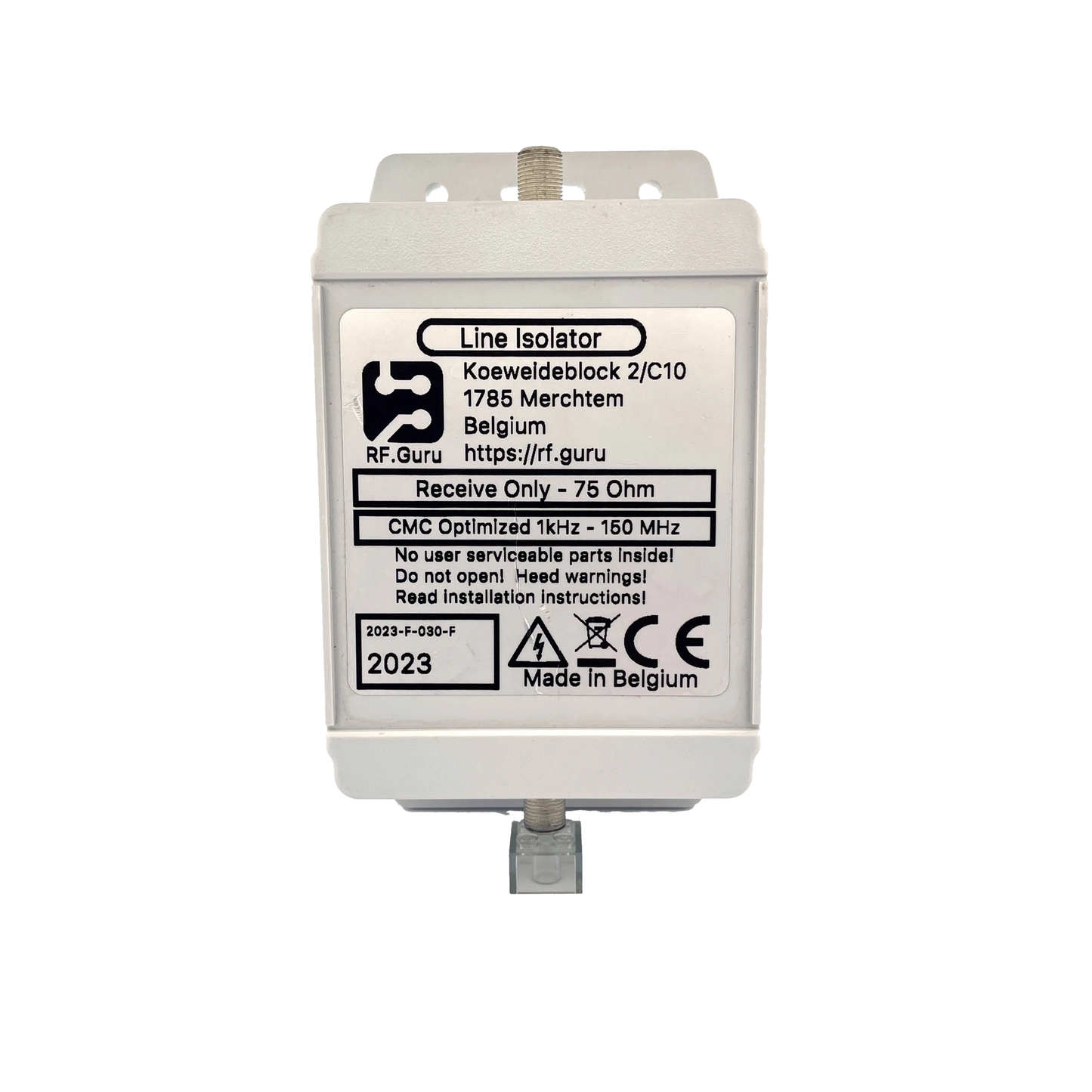
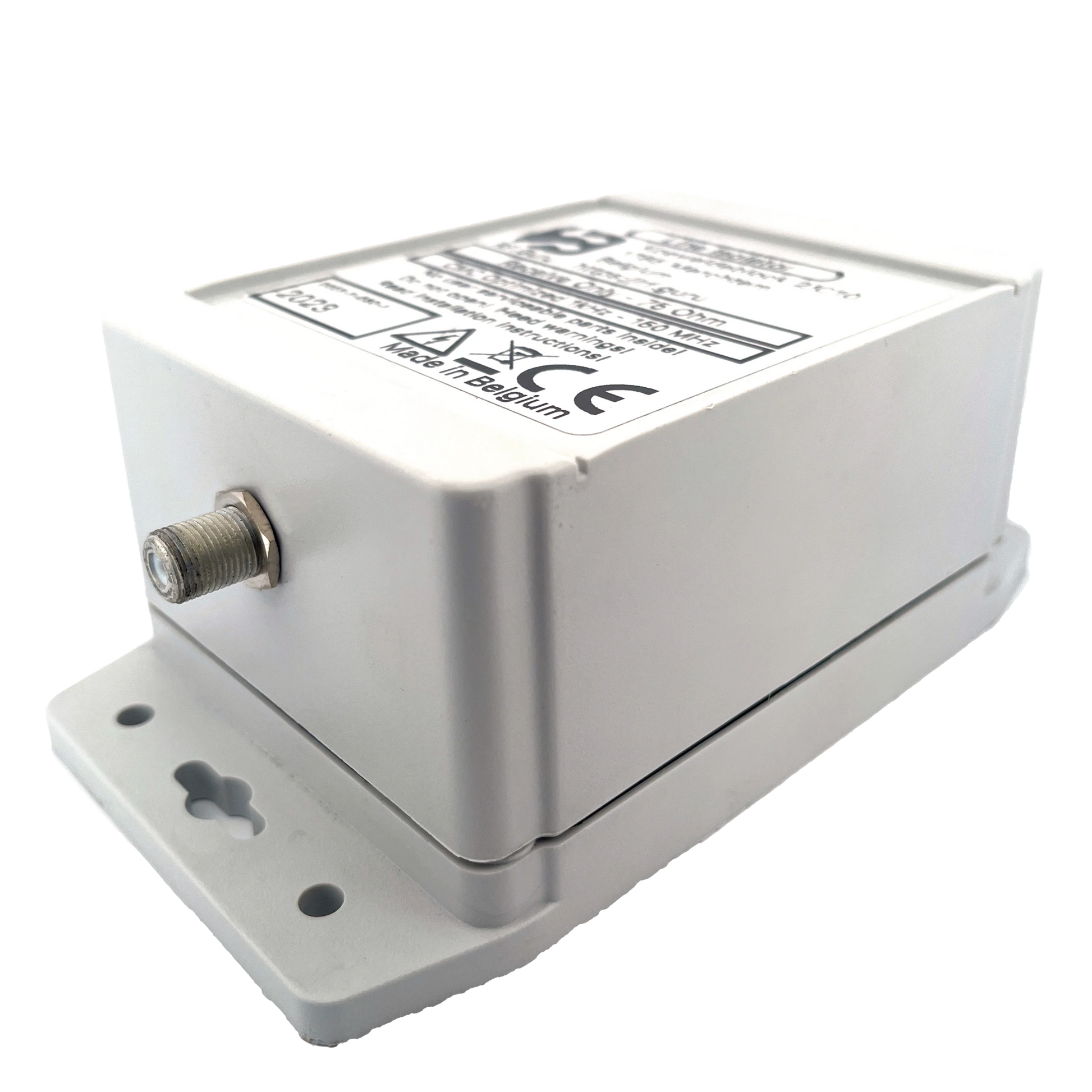
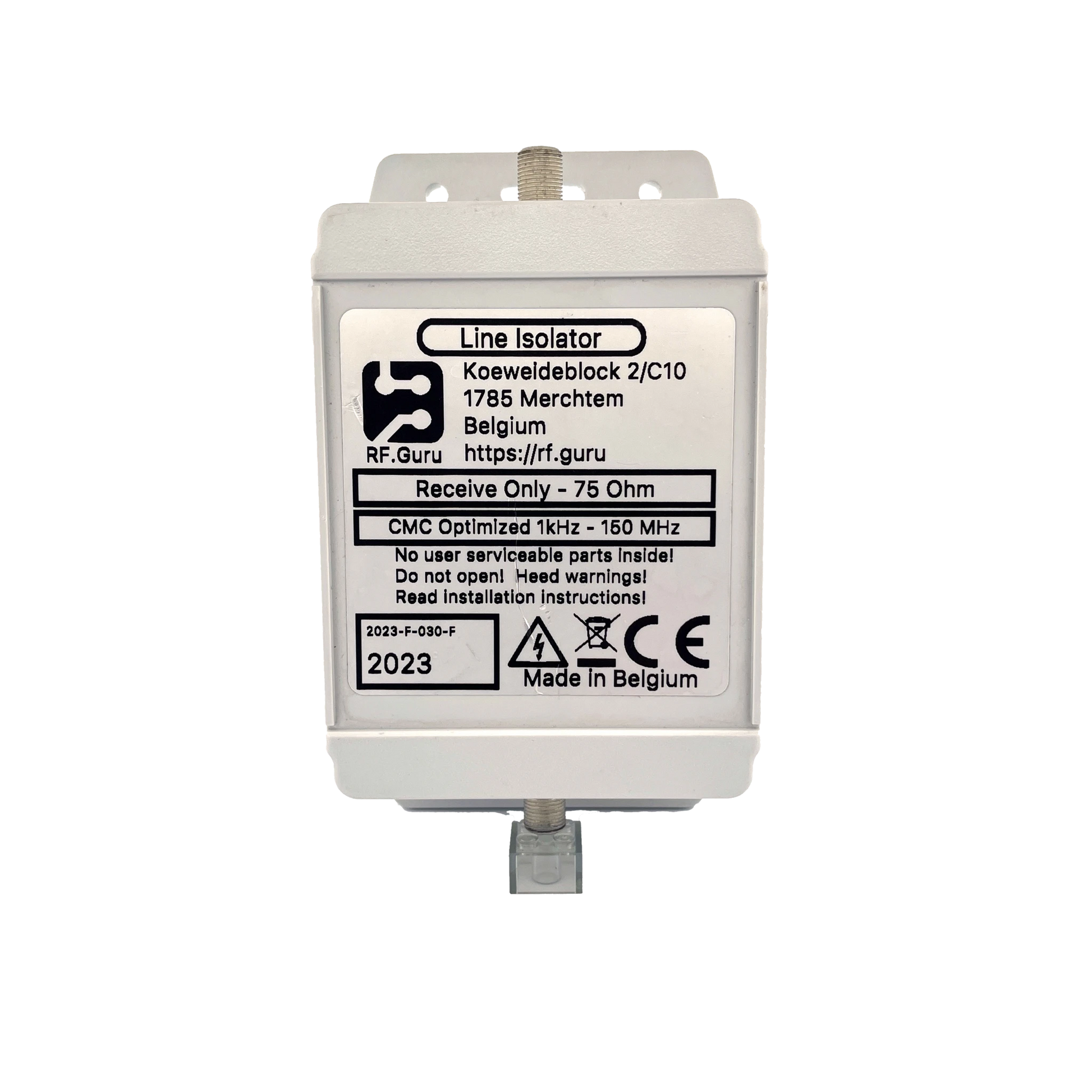
This wideband receive / low-to-medium-power HF choke uses a unique three-ferrite-type cascade (three mixes in series, 18 turns per core) to achieve ultra-high choking from the LF bands up through HF. Available in **50 Ω** (PL-259 / N-type) and **75 Ω** (**F-connector**) versions for SDRs and active-antenna systems.
Baluns in a Nutshell
Why “Common-Mode” Is the Most Abused Term in Ham Radio
How Much Choking Do You Really Need — for RX and TX?
Built for the Long Run
Every housing is HV-coated inside and out for corrosion resistance, including salt exposure. The polycarbonate enclosure uses silicone gaskets and a decompression valve, ensuring a long-life outdoor seal. Perfect near E-probes, active antennas, SDRs, and shack entry points.
Installation Guidance
For maximum suppression, install it at the antenna using a 25–50 cm jumper. A second choke at the shack entrance is strongly recommended to keep RF outside and prevent noise coupling into audio or mains systems.
Measured Common-Mode Performance
Conservative, real-world values measured using our EMC-standard dual-probe CM method.
| Region / Band | Representative Frequency | Choking |Z| (Ω) | Impedance-Equivalent dB (from |Zc|, 50 Ω ref) |
Impedance-Equivalent dB (from |Zc|, 75 Ω ref) |
|---|---|---|---|---|
| ULF | 1 kHz | ≈ 36 Ω | 4.7 dB | 3.4 dB |
| VLF | 10 kHz | ≈ 360 Ω | 18 dB | 15 dB |
| LF | 100 kHz | ≈ 3.6 kΩ | 37 dB | 34 dB |
| MF | 1 MHz | ≈ 36 kΩ | 57 dB | 54 dB |
| HF Amateur Bands (Peak Choking) | ||||
| 160 m | 1.9 MHz | ≈ 25 kΩ | 54 dB | 51 dB |
| 80 m | 3.5 MHz | ≈ 35 kΩ | 57 dB | 53 dB |
| 40 m | 7.0 MHz | ≈ 50 kΩ | 60 dB | 56 dB |
| 20 m | 14.2 MHz | ≈ 40 kΩ | 58 dB | 55 dB |
| 15 m | 21.2 MHz | ≈ 30 kΩ | 56 dB | 52 dB |
| 10 m | 28.4 MHz | ≈ 20 kΩ | 52 dB | 49 dB |
| *Impedance-Equivalent (dB) values are computed directly from measured |ZCM| using 50 Ω or 75 Ω common-mode reference impedances. Real antennas rarely present 50/75 Ω CM, so these values represent the choke’s intrinsic suppression capability — not the attenuation you would see on a specific antenna system. More background: Why dB Attenuation Specs on Ham Chokes Are a Mess.* | ||||
| All measurements are conservative and verified with three ferrite types in series (18 turns per core) using 75 Ω coax. | ||||
Construction Highlights
- Triple-ferrite cascade (three mixes in series)
- 18 turns per core using thin PTFE coax (50 or 75 Ω)
- HV-treated housing interior + exterior
- Polycarbonate enclosure, silicone gaskets
- Decompression valve for pressure equalization
- Connectors: PL-259, N-type (50 Ω) or F-connector (75 Ω)
- All values are conservative and load-verified
RF.Guru uses EMC-standard dual-probe common-mode measurement. One probe injects controlled CM current; a second probe measures the CM current at the output.
This produces true Common-Mode Rejection (CMR) — actual CM current suppression under load — not differential-mode impedance artifacts from VNA sweeps.
Typical VNAs excite the feedline in differential mode. Our EMC dual-probe setup measures real CM suppression exactly as it appears on receive antennas and feedlines.
Mini-FAQ
-
Q: Is this choke usable for TX?
— Yes, at moderate power. For QRO use the dual-core versions. -
Q: Waterproof?
— Yes — gasket-sealed and pressure-equalized. -
Q: One choke or two?
— Best practice: one at the antenna + one at the shack entry. -
Q: Available connectors?
— PL-259 / N-type (50 Ω) or F-connector (75 Ω). -
Q: Are the numbers real?
— Yes. All values are conservative, verified under real CM load.
Interested in more technical content? Subscribe to our updates.
Questions or experiences to share? Contact RF.Guru.
Share