RF Guru
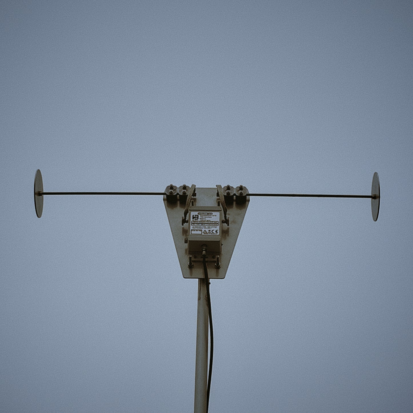
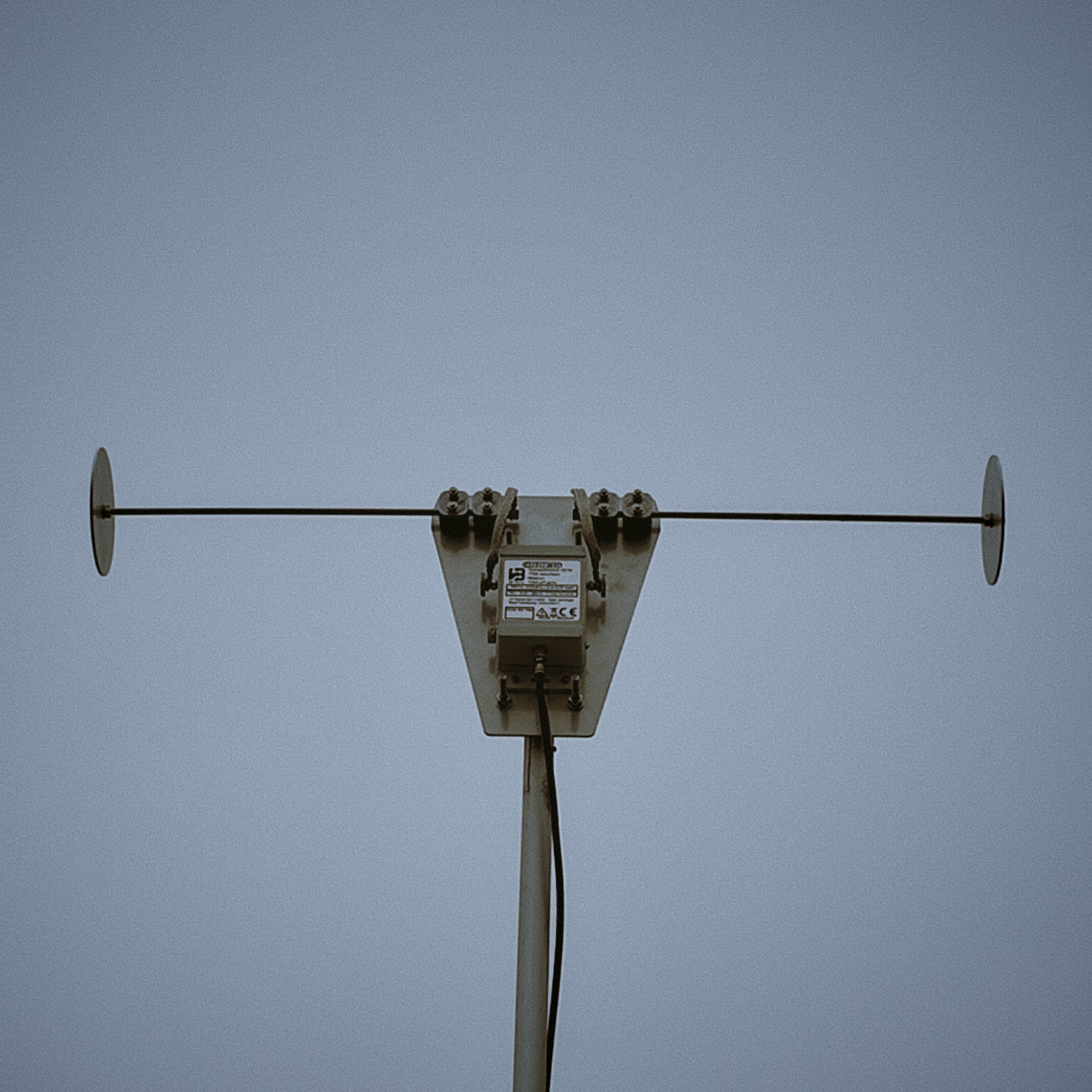
SkyTracer2 — Shorted Active Loaded Dipole — 500 KHz - 30 MHz
SkyTracer2 — Shorted Active Loaded Dipole — 500 KHz - 30 MHz
Couldn't load pickup availability
If you order coax cables together with connectors, we will crimp the connectors for free before shipping.
All our products are handmade, and fulfilment times may vary depending on order volume. Please allow 2–3 weeks for your order to be completed and shipped.
Listen to our SDRs
Hear SkyTracer2 and our other antennas live on remote SDRs.
Included
-
SkyTracer2 (choose one configuration):
- Standard: 0.5 m arms with 15 cm diameter capacitive end-disks
-
MAXI: 1 m arms, no capacitive end-disks (more gain on 160–80 m)
- ULTRA: 1 m arms, with 15 cm diameter capacitive end-disks (more gain on 600m-80m)
- Stainless Steel (RVS316) mounting bracket
- Bias-T (13.8 V) — F-type to SMA
- Short SMA-to-BNC patch
- 1 meter long 13.8 V DC power cable with Powerpole connectors
Optional
- 10 m INTSAT-170-ELITE 75 Ω coax (2× F-type connectors)
- RVS Ground Peg (with F bulkhead) + RX Line Isolator
Description
SkyTracer2 is a precision active shorted E-dipole. The Standard version adds capacitive hats to strengthen low-band response; the MAXI version uses longer arms without hats for more output on 160–10 m; the ULTRA has even more gain on the 600-160m band. It exhibits deep, loop-like nulls and directionality that depend on the arrival angle of incoming waves. Coverage spans 500 kHz–30 MHz on all versions!.
Key Features
- Wideband coverage: 0.5–30 MHz reception
- Three versions: Standard (0.5 m + hats) and MAXI (1 m, no hats) and ULTRA (1m + hats)
- High-linearity front-end: dual, push-pull low-noise gain stages for strong large-signal handling
- Pre-LNA filtering: dedicated FM-broadcast and 50 MHz notch sections ahead of gain
- Input protection & CMR: common-mode choke plus limiter/ESD network at the feedpoint
- Transformer-coupled output: broadband RF transformer with post-filtering and ESD at the F-connector
- Built-in RF limiter: tolerant near QRO (keep ≥ 8 m separation)
- Horizontally polarized with excellent common-mode rejection
- Powering: 13.8 V via bias-T; local regulated rails (~10 V) with RF chokes and robust decoupling
- Critical capacitors use stable NP0/COG dielectrics
Optimized for 160–20 m coverage. On these bands SkyTracer2 provides strong sensitivity, deep nulls, and excellent SNR. Above ~20 MHz (15–10 m) it remains usable, but efficiency decreases and nulls become shallower. For upper HF (20–10 m) users seeking more balanced response, consider the OctaLoop Mini, tuned for 1–30 MHz with more uniform performance across 40–10 m.
Deep Nulls

Operating Guidance
Standard (160–10 m)
- HF 1–10 MHz: NVIS / regional work
- HF 14–30 MHz: DX (slightly less gain on 160M band)
Best height: 5–6 m — mixed NVIS + mid-angles (≈1–14 MHz), still effective up to 30 MHz.
MAXI (160–10 m)
- HF 7–10 MHz: strong NVIS
- 1–30 MHz: DX (a bit more gain than Standard)
Best DX height: 6–8 m — lowers the main response from zenith to capture typical DX arrival angles.
ULTRA (600–10 m)
- HF 7–10 MHz: strong NVIS
- 1–30 MHz: DX (a bit more gain than MAXI ideal for 600/160)
Best DX height: 6–8 m — lowers the main response from zenith to capture
Applications
- Amateur-radio HF reception (160–10 m)
- Shortwave broadcast monitoring
- HF propagation studies & experimentation
- Portable/field reception & educational labs
Installation & Use
Mount the active head on a clear mast, connect the 75 Ω feedline, and power via the included 13.8 V bias-T. For best common-mode rejection, use an RX line isolator near the antenna and a second before the coax enters the shack. Add the RVS ground peg if you want a hard RF reference at the feed.
Mini-FAQ
- Standard vs MAXI? Standard: 0.5 m arms with 15 cm diameter hats for 160–10 m. MAXI: 1 m arms, no hats, more gain on 160–10 m, ULTRA: even more gain!
- Power & biasing? 13.8 V through the bias-T; the head regulates locally (~10 V) with RF chokes and decoupling.
- Nearby transmit antennas? Yes, but keep ~8 m separation; the built-in limiter protects the front-end.
- Recommended height? Standard: 5–6 m for mixed NVIS/mid-angles. MAXI: 6–8 m for DX angles.
- CMR best practice? Use RX line isolators (one near the antenna, one before the shack). Add the RVS ground peg for a hard RF reference.