RF Guru
TerraBooster2 — Active shielded 'Loop on ground' — 500KHz - 30MHz
TerraBooster2 — Active shielded 'Loop on ground' — 500KHz - 30MHz
Couldn't load pickup availability
If you order coax cables together with connectors, we will crimp the connectors for free before shipping.
Listen to our SDRs
Hear TerraBooster2 and our other antennas live on remote SDRs.
Listen to our SDRs
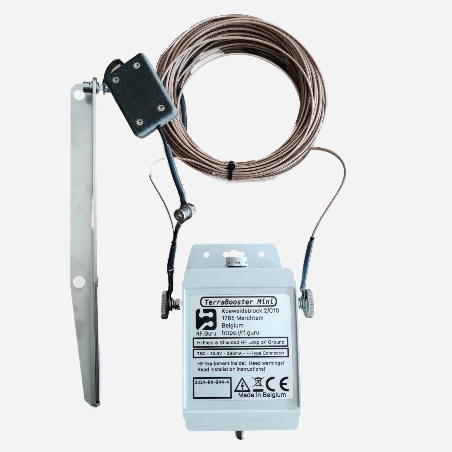
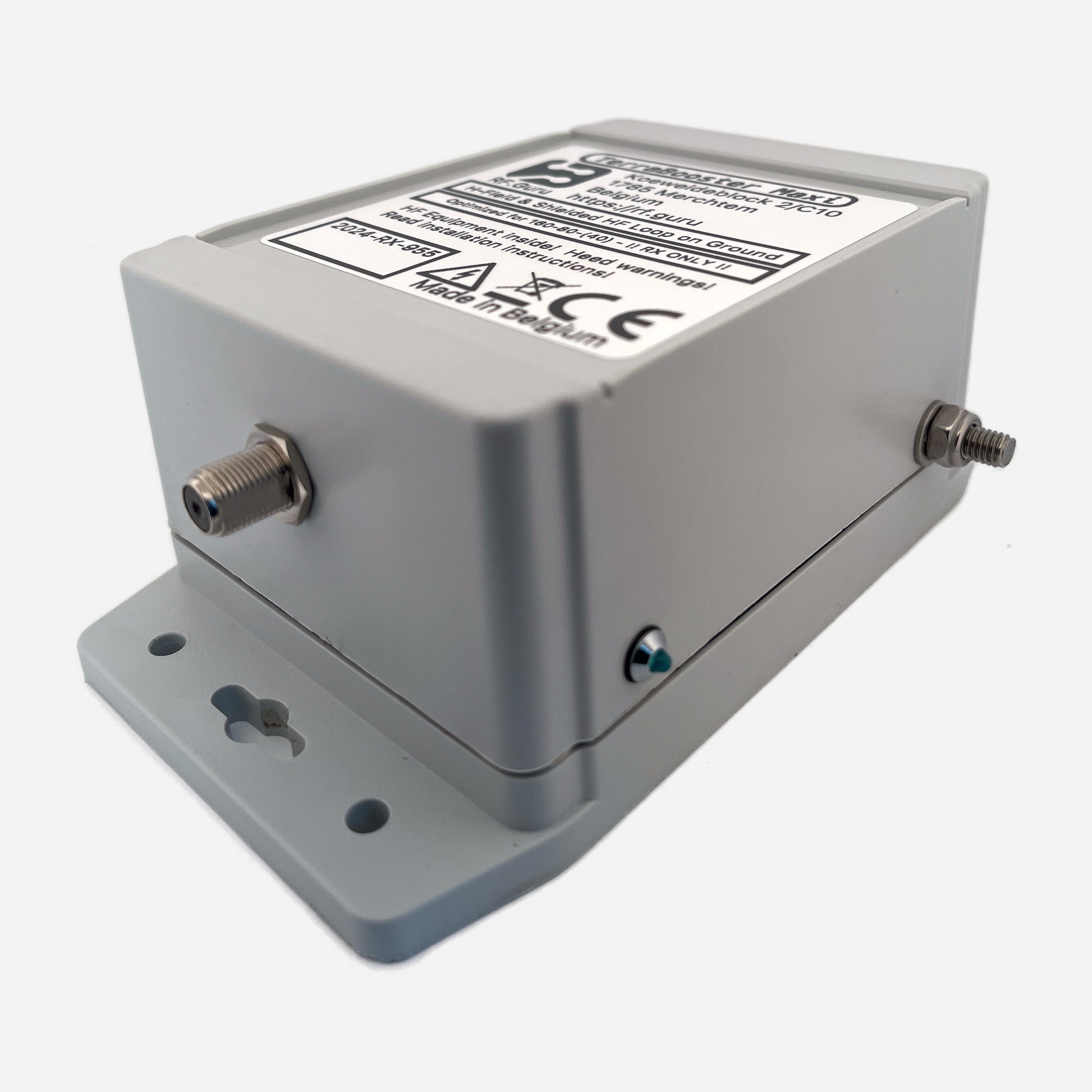
The TerraBooster2 is a cutting-edge HF active shielded H-field loop-on-ground system in four sizes: Mini (16 m), Medi (32 m), Maxi (56 m) and Xtreme (84 m, unshielded wire). It’s engineered for exceptionally low-noise reception across HF.
All shielded models use RG178B/U coax for the loop element. The Xtreme uses antenna wire (unshielded). The loop braid in shielded models is tied to ground through an integrated RF filter to reduce E-field pickup and lower ambient noise.
Key Features
- Dual-MMIC push-pull amplifier: +41 dBm IIP3
- Very low internal noise floor
- 500 kHz – 30 MHz operating range
- Integrated RF limiter and ESD protection
- FM broadcast notch + 50 MHz low-pass
- Wideband common-mode choke on feed
- 10 V regulated internal rail
- Mild, useful directionality
What’s Included
- TerraBooster2 Active Unit
- TerraBooster GAP box … adds a 4 cm gap on the side opposite the feedpoint.
- Loop element: 16 m / 32 m / 56 m RG178B/U (Mini/Medi/Maxi) or 84 m FS2 wire (Xtreme) (Xtreme does not have a GAP box)
- Bias-T with integrated line isolator
- SMA-to-BNC adapter
- 1 meter long 13.8 V DC power cable with Powerpole connectors
- a RVS high-impedance ground pegs
- RC bleed-off filter (shielded models)
- Inline selectable attenuator: 3 dB, 6 dB, 10 dB, 13dB, 16dB, 19dB
RX 75 Ω line isolator — install before coax enters shack
INTSAT-170-ELITE 75 Ω coax (long/short runs)
F-type compression connectors (indoor/outdoor)
Design Philosophy
The TerraBooster2 uses H-field coupling instead of E-field sampling. Shielded versions reference the braid through a controlled RF filter, yielding lower noise than passive LoGs and better isolation from local electronics. The Xtreme trades shielding for maximum capture area, producing stronger DX performance on 30–10 m.
Directional Characteristics
All models show a broad cardioid-like pattern with maximum response perpendicular to the loop. Rotating the loop allows localized noise nulling.

Model Performance Summary
Compact comparison of gain trend and elevation-angle behaviour. Full modelling is available in the Technical Overview.
| Model | Loop Size | Elevation Behaviour | Band Emphasis | Notes |
|---|---|---|---|---|
| Mini | 4 × 4 m | Steep NVIS (60–85°) | 160–40 m | Highest-angle; very quiet |
| Medi | 8 × 8 m | NVIS + mid-angle (40–70°) | 80–30 m | Balanced skip + NVIS |
| Maxi | 14 × 14 m | ~30° DX + NVIS shelf | 160–20 m | Strong DX on low/mid HF |
| Xtreme | 21 × 21 m | 10–20° DX on 30–10 m; 15–25° DX on 40 m | 40–10 m | Low-angle longwire-like behaviour |
Why Elevation Angles Differ Between Models
All TerraBooster2 loops sit only 5–10 cm above ground, so their NVIS lobes look broadly similar. But the loop length relative to wavelength determines how much energy is pulled down into mid- and low-angle DX lobes:
- Mini — Short wire ≪ λ → mostly steep NVIS
- Medi — More mid-angle response
- Maxi — Strong ~30° DX lobe on 160–20 m
- Xtreme — Longwire-like; 10–20° DX on 30–10 m and lower 40 m DX angle
The Xtreme’s 21 × 21 m loop is ~84 m perimeter: ≈ 2.1 λ on 40 m. This naturally produces a stronger low-angle (15–25°) lobe — which is why it hears DX on 40 m even when smaller loops remain NVIS-heavy.
Exact angles depend on soil/moisture, but the model-to-model trends are robust.
Mounting & Placement
- Lay 5–10 cm above ground
- Keep away from buildings/electronics
- Use the supplied RVS ground pegs
- Line isolator recommended at shack entry
Grounding Advice
- Center reference peg — required for all versions
- Shield reference peg — required for Mini/Medi/Maxi
- Place pegs ~20 cm apart
Inline Attenuators (6/10/20 dB)
Included to ensure optimal SNR with short coax runs. Install only on the radio side of the Bias-T. Target: 3–6 dB noise rise when connecting the antenna.
Technical Specifications
| Parameter | Specification |
|---|---|
| Frequency Range | 500 kHz – 30 MHz |
| IIP3 | +41 dBm |
| Output Impedance | 75 Ω |
| Connectors | F-type (RF), SMA (output) |
| Power (Bias-T) | 13.8 V, ~180 mA |
| Internal Rail | 10 V regulated |
| Mounting | Ground-mounted (5–10 cm) |
Mini-FAQ
- Ground pegs required? Yes — 1 for all models, 2 for shielded models.
- Low-angle DX? Maxi (~30°), Xtreme (10–20°).
- Local noise issues? Rotate the loop; broad cardioid behaviour helps.
- Long coax? Use INTSAT-170-ELITE 75 Ω.