RF Guru
6kW VertiCore ¼λ – 5/8λ 4M 6M 10M 12M 15M 17M 20M
6kW VertiCore ¼λ – 5/8λ 4M 6M 10M 12M 15M 17M 20M
Couldn't load pickup availability
VertiCore: A Measured 50 Ω Vertical Without Loading Coils or Traps
Choose a band-specific ¼λ or 5/8λ radiator, a tested high-power 1:1 balun option and the matching elevated-radial assembly.
VertiCore is assembled as a band-specific antenna system. Fulfilment normally takes 1–3 weeks depending on order volume.
The radiator connection, elevated radial plane and 1:1 balun are treated as one measured feed assembly—not as interchangeable catalogue parts.
How VertiCore reaches its intended feed impedance: the coax is not connected at the mechanical end of the radiator. The driving point is moved a short distance upward on the radiating tube, and the four-radial plane moves upward with it. RF.Guru establishes that position on the finished band-specific structure by measurement. It is deliberate antenna geometry, not a hidden impedance-transforming coil.
Choose the Band Geometry
Selected where the complete installed geometry is intended to favour a strong low-elevation component. The real pattern still depends on height, ground, radial symmetry, mast, feedline and surroundings.
A direct, predictable vertical system using four elevated 45° quarter-wave radials and the same controlled-feedline philosophy.
The Feed Assembly Is the Design
Moving the radiator connection and radial plane changes the driving point of the complete antenna. It does not rely on a series loading coil, trap or concealed impedance ratio.
The four quarter-wave radials are part of the RF circuit, match and pattern. Their installed height, angle and symmetry matter.
The tested balun option limits unwanted outside-of-coax current. The antenna geometry establishes the nominal feed impedance.
Available Configurations
| Band group | Radiator geometry | Radial assembly | Operating character |
|---|---|---|---|
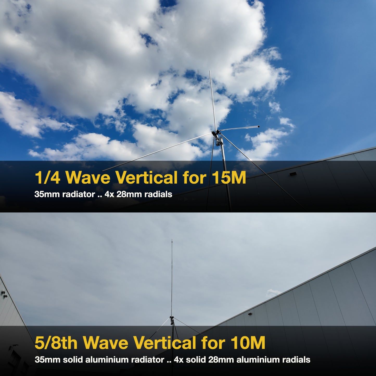
| 4 m, 6 m, 10 m, 12 m | Band-specific 5/8λ | Four elevated 45° ¼λ radials | Low-elevation emphasis for DX, terrestrial openings and sporadic-E where applicable |
| 15 m, 17 m, 20 m | Band-specific ¼λ | Four elevated 45° ¼λ radials | Simple monoband vertical response with an intentionally controlled return system |
Choose the Balun Service Class
| Option | What is qualified | Selection boundary |
|---|---|---|
| 6 kW 1:1 balun | RF.Guru production option measured and tested for the intended antenna assembly | Choose for stations whose waveform, duty cycle, mismatch and ambient conditions remain inside the 6 kW option's service envelope |
| 9 kW 1:1 balun | Higher-service production option measured and tested as a distinct balun assembly | Choose where additional voltage, current and thermal margin is required; installation and legal-power limits still apply |
A power label is not an operating licence or a universal all-mode guarantee. Waveform, PEP, average power, duty cycle, tune time, mismatch magnitude and phase, connector and feedline ratings, ambient temperature, sun and ventilation all affect the finished station boundary. Digital modes require particular attention to average heating.
What Is Included?
Band-specific offset feed structure, four-arm radial hub, selected 6 kW or 9 kW 1:1 balun and stainless mounting hardware.
Select a pre-tuned ¼λ or 5/8λ aluminium radiator and radial set for the required band, or choose the DIY mechanical option.
Materials and Installation
- Radiator: marine-grade aluminium tubing without loading coils or traps.
- Hardware: RVS/INOX 316 stainless fasteners and fittings.
- Radial plane: install elevated and symmetrical, with the 45° radial tips clear of people, structures and conductive surfaces.
- Feedline route: initially route the coax away from the radial plane at right angles and avoid letting it run alongside a radial or radiator.
- Final verification: measure complex impedance/SWR at the feedpoint after the mast, radials, coax and nearby conductors are in their operating positions.
Installation changes the measured antenna. Feedpoint height, radial symmetry, soil, mast coupling, nearby roofs and wiring can shift impedance and pattern. Fine adjustment should preserve the designed relationship between the radiator connection and the radial plane; do not move one casually without rechecking the complete system.
Maintenance
Use AL-1100 aluminium paste on clean aluminium-to-aluminium interfaces during assembly. Inspect joints, stainless hardware, balun enclosure, connector weatherproofing, radial symmetry and feedline strain relief periodically; shorten the interval in coastal or polluted environments.
Technical Documentation
The overall architecture, band choices and installation concept.
Why the quarter-wave geometry is used for the longer-band versions.
The longer-radiator option and its installed-system considerations.
How the offset driving point, radial return, common-mode control and QRO boundary fit together.
Prefer a general update index? Visit the RF.Guru subscription page. For ordering, installation or configuration questions, contact RF.Guru.
Follow the Current Path, Not the Folklore
Explore more RF.Guru technical deep dives on transmission lines, common-mode current, baluns, chokes and antenna measurement—and subscribe for new engineering articles and laboratory notes.
Join the notification list →Mini-FAQ
- How does VertiCore reach approximately 50 Ω without a base coil? The feed connection is moved a short distance upward on the radiator and the elevated radial plane moves with it. RF.Guru establishes the band-specific driving point by measuring the finished assembly.
- Does the 1:1 balun transform the antenna impedance to 50 Ω? No. The antenna geometry establishes the nominal feed impedance. The 1:1 balun controls common-mode feedline current.
- Which bands use the 5/8λ version? The 4 m, 6 m, 10 m and 12 m variants use band-specific 5/8λ radiators. The 15 m, 17 m and 20 m variants use ¼λ radiators.
- Can I install the radial hub at any height on the tube? No. The radiator connection and radial plane form a measured geometry. Moving either one changes the antenna and requires a complete feedpoint recheck.
- Do I need an antenna tuner? A correctly assembled and installed monoband VertiCore is designed for an approximately 50 Ω feed without a tuner. Nearby structures and installation errors can still move the impedance.
- What is the difference between the 6 kW and 9 kW choices? They are separately measured and tested balun service options. Select the required voltage, current and thermal margin while respecting waveform, duty cycle, mismatch, installation and legal-power limits.
Share