RF Guru
3.6kW XentrX 40M - 6M
3.6kW XentrX 40M - 6M
Couldn't load pickup availability
Updated October 2025
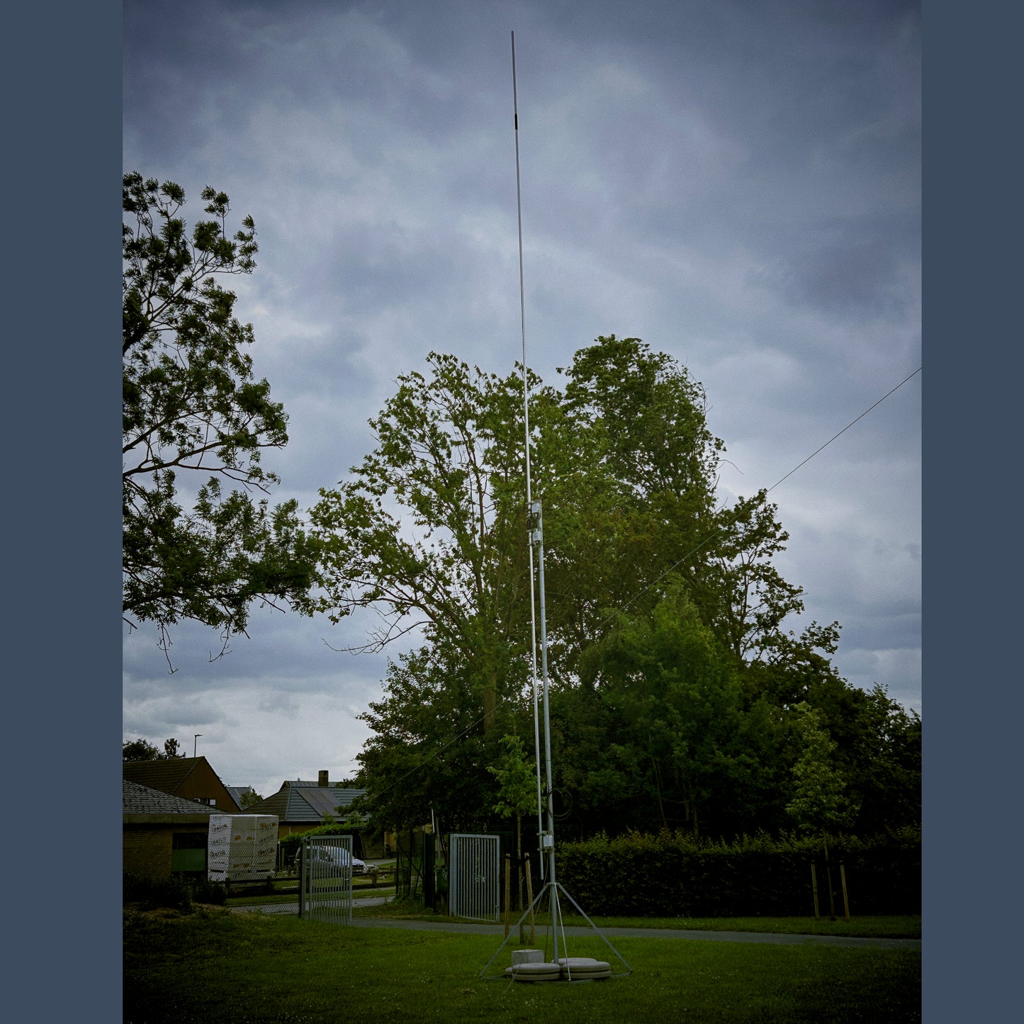
XentrX 40–6 m Off-Center Vertical Dipole
The XentrX 40–6 m Off-Center Vertical Dipole is a high-efficiency broadband HF vertical designed for operators seeking full-band coverage and mechanical strength without traps, coils, or external radials. It covers all amateur bands from 40 m through 6 m with stable impedance, rugged weatherproofing, and 3.6 kW PEP power capacity.
Mechanical Construction
The radiator uses a dual-tube structure: a thick outer aluminum tube reinforced with a concentric inner tube for maximum stiffness. Each meter section is indexed at 60° rotational offsets, mechanically locking the elements to prevent twisting or creeping under torque. Built from marine-grade AL-1100 aluminum and stainless hardware, the XentrX maintains alignment and durability under severe wind conditions.
The antenna can be installed freestanding using the RF.Guru ballast frame or on a rigid tower or mast (up to 6 m). When used without the ballast frame, non-conductive guy wires are advised to maintain perfect vertical alignment and minimize lateral stress.
Electrical Design
At the core is the RF.Guru 3.6 kW PEP Dual-Core 4 : 1 UNUN — a low-loss broadband impedance transformer ensuring smooth matching from 200 Ω to 50 Ω. The supplied top and bottom chokes suppress both transmit return currents and received common-mode noise, keeping the system balanced and reducing interference pickup on the feedline.
Across the full 40 – 6 m range, SWR remains below 3 : 1 except for 30 m (≈ 3.4 : 1), which most internal tuners can easily manage. For all other bands, the transceiver’s internal tuner is entirely sufficient; only on 30 m might some rigs need an external tuner depending on their matching range.
Performance of Integrated 4 : 1 UNUN
| Parameter | Specification |
|---|---|
| Impedance ratio | 4 : 1 (200 Ω → 50 Ω) |
| Power handling | 3.6 kW PEP @ VSWR < 2 : 1 |
| Continuous carrier (CCS) | 1.8 kW PEP @ VSWR < 2 : 1 |
| FT8 / FT4 operation | 1.25 kW PEP @ VSWR < 1.5 : 1 |
| Recommended de-rating | VSWR > 3 : 1 → < 900 W PEP • VSWR > 5 : 1 → < 450 W PEP |
| Operational range | 1.5 – 30 MHz |
| Insertion loss | < 0.3 dB |
| Intrinsic VSWR | < 1.3 : 1 (across band) |
Installation & Mounting
The RF.Guru ballast frame provides the most stable foundation for the XentrX. For best performance, place a rubber mat 3 – 5 cm thick beneath the ballast frame. This damping layer absorbs subtle motion from wind and mast sway, preventing micro-slippage between ballast blocks and distributing load evenly on irregular surfaces — dramatically improving long-term stability and reducing mechanical stress at the mast base.
If installing on a tower or mast, ensure adequate stiffness and use non-conductive guy wires to maintain geometry and prevent pattern distortion.
- 7.40 m radiator and 4.65 m counterpoise (if ordered with aluminum tubes — if not, only assembly hardware is included)
- 3 mounting plates
- 2 glass-fiber-reinforced tubes (one for extending the 6 m mast to 7.40 m and one as a center alignment pin between radiator and counterpoise)
- 1 × 4 : 1 UNUN (auto-transformer, dual-core)
- 2 × 1 : 1 current baluns (30-10M band optimized single core on top and windeband 160-10M optimized on bottom)
- 1 m coax jumper (between the 4 : 1 UNUN and first current balun)
- 8 m coax (between the first and second current balun)
- Stainless hardware and weather-sealed connectors
VSWR Sweep Across 40 – 6 m Bands
 XentrX 40–6 m indicative SWR sweep (feedpoint measurement, 40 m – 6 m range)
Radiation Characteristics & Operating Angles
(Assumed configuration: upper arm 7.40 m, lower arm 4.65 m, 14 cm gap, feedpoint is about 6 m high, ≈ 15 cm from mast, average ground εr ≈ 13 / σ ≈ 5 mS/m)
Elevation angles are measured above the horizon; azimuth is effectively omni. Reference for 0 dBd = 2.15 dBi. Values below represent peak directivity relative to a free-space half-wave dipole (typical on-air gain ≈ 1 – 3 dB lower after losses).
| Band | Electrical Length (≈ 12.05 m / λ) | Primary TOA (°) | Secondary Lobes | Peak Gain vs 0 dBd* | DX / NVIS Notes |
|---|---|---|---|---|---|
| 40 m (7.1 MHz) | ~0.29 λ | 20 – 25° | small lobe ~60 – 70° | +1.0 – +1.5 dBd | Regional–DX; NVIS poor. |
| 30 m (10.1 MHz) | ~0.40 λ | 17 – 20° | weak mid-angle ripple | +1.5 – +2.0 dBd | Strong DX band; NVIS poor. |
| 20 m (14.1 MHz) | ~0.56 λ | 12 – 16° | notch ~30° | +2.0 – +2.5 dBd | Excellent DX; NVIS poor. |
| 17 m (18.1 MHz) | ~0.73 λ | 10 – 14° | ~35 – 40° lobe | +2.0 dBd | DX-favoured; split-lobe begins. |
| 15 m (21.2 MHz) | ~0.85 λ | 10 – 12° | 25 – 30° & 50° | +1.5 – +2.0 dBd | DX; multiple lobes. |
| 12 m (24.9 MHz) | ~1.00 λ | 8 – 12° | 35 – 45° | +1.0 – +1.5 dBd | DX-good; higher-angle lobe. |
| 10 m (28.5 MHz) | ~1.15 λ | 6 – 10° | multi-lobed to 55° | +0.5 – +1.5 dBd | DX & E-skip; multi-lobed. |
| 6 m (50 MHz) | ~2.0 λ | 5 – 8° | many mid/high lobes | 0 – +1.0 dBd | E-skip/TEP |
*Peak pattern gain with ideal efficiency; subtract ≈ 1 – 3 dB for on-air values.
Practical Takeaways
- DX capability: Anything with TOA ≤ 20° is DX-friendly — achieved on all bands; best on 20 – 10 m.
- NVIS: Verticals suppress 60 – 90° angles; not suited for local NVIS work.
- Why low angles dominate: Ground image currents reinforce the horizon; longer elements add lobes but keep a strong low-angle component.
- Azimuth: With 15 cm mast offset and dual chokes, pattern is effectively omnidirectional.
Tips to Reduce Take-Off Angle Even Further
- Raise the antenna by 2 – 3 m to lower the TOA a few degrees.
- Keep common-mode currents minimal (using both 1 : 1 chokes).
- Use average or moist ground to reinforce low angles (dry soil pushes energy higher).
Mini-FAQ
- Does the XentrX require radials? — No. It’s an off-center vertical dipole; the lower section acts as a counterpoise.
- What tuner do I need? — Most internal tuners work on all bands except 30 m (some may need an external unit).
- Why two chokes? — To suppress return currents on TX and reduce noise pickup on RX.
- Power handling? — 3.6 kW PEP (1.8 kW CCS) with integrated dual-core UNUN.
Interested in more technical content? Subscribe to our updates for deep-dive RF articles and lab notes.