RF Guru
VertX 20–10 m Multiband HF Vertical
VertX 20–10 m Multiband HF Vertical
Couldn't load pickup availability
VertX: Fewer Resonators, Better-Controlled Currents
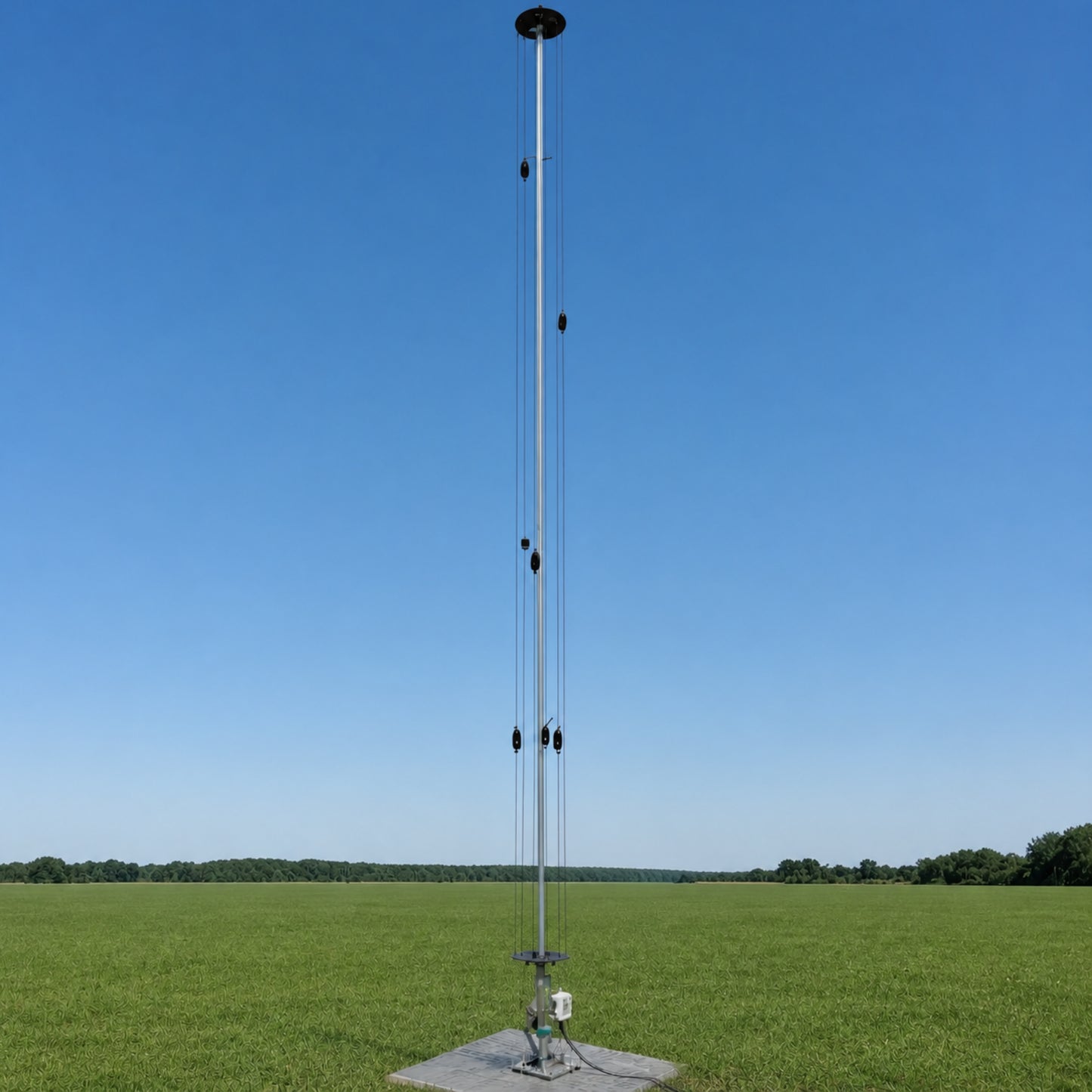
A deliberately simplified upper-HF vertical: the aluminium tube serves 20 m, one wire serves 15 m, three staggered wires serve the wide 10 m allocation, and 12 m/17 m are tuner-assisted.
VertX is assembled around the selected mechanical and balun options. Fulfilment normally takes 1–3 weeks depending on order volume.
RF.Guru removed two dedicated nearby-band resonators after the denser geometry added interaction and tuning effort that did not justify their place.
What the analyser cannot decide alone: trimming or tuning can restore the impedance presented to a transmitter while current amplitude, phase, loss and elevation pattern remain changed. VertX is designed around branch-current control, not only low SWR.
The Current Radiator Architecture
The conductive tube is the principal 20 m radiating element. It works against the installed on-ground radial return system.
A single resonant branch keeps the directly selected 15 m current path straightforward.
The Belgian allocation spans 28.000–29.700 MHz. Three nearby resonances broaden useful coverage while keeping the tested VertX geometry deliberately compact.
No separate resonators are added between the neighbouring bands. Match, tuner/feedline loss, current distribution and pattern remain separate verification questions.
Why Not One Wire for Every Band?
Twelve metres is close to the 10 m and 15 m conductors; 17 m is close to the 15 m wire and 20 m tube. These branches share a feedpoint, radial system and near field. Adding resonators can move several impedances and redistribute current.
RF.Guru measured the denser radiator set and chose the reduced architecture. This does not mean every dense fan vertical fails. It means an added wire must earn its coupling and mechanical complexity through current and pattern evidence—not only by creating another SWR dip.
What the A/B/B/A Receive Comparison Showed
RF.Guru compared VertX with a DX Commander at the same test site using the same A/B/B/A sequence used for receive-antenna evaluation. Across the repeated swaps, VertX was consistently favoured on receive; the difference was most obvious on 10 m, 12 m and 15 m. On 17 m and 20 m, the two antennas were broadly on par.
The result is real; the cause remains a working hypothesis. The reduced interaction between nearby radiators is the leading explanation, but that site did not permit RF.Guru's drone-borne oscillator method for plotting a far-field pattern. The comparison therefore supports the design decision without claiming a measured gain figure or a fully isolated pattern mechanism.
It can present an acceptable impedance to the transmitter on 12 m and 17 m. It does not certify efficiency or takeoff angle.
The installed radiator currents, ground, radials, feedline, mast and surroundings establish the elevation pattern.
The location keeps the mechanical and radial-current geometry deliberate. It is not presented as an automatic performance gain.
Choose the Ground-Radial System
VertX uses on-ground radials as the intended RF return. The options follow the measurement boundary established by Rudy Severns, N6LF: radial count, length, soil and frequency interact. More shorter wires are not automatically better.
| Optional kit | Use it when | Engineering boundary |
|---|---|---|
| 16 × 5 m radials | You need a compact baseline with useful long coverage | A credible starting field, not a perfect ground plane on every soil |
| 24 × 5 m radials | You want an all-equal step up to 120 m of useful-length wire | Lower loss still depends on soil, layout and the complete installation |
| 32 × 5 m radials | You want the densest all-equal option with 160 m of useful-length wire | No universal optimum independent of soil, spacing and surroundings |
Install the radial field before final tuning. Spread radials as evenly as the site permits, preserve the full five-metre conductor length where possible, route the coax deliberately and measure the complete antenna. The 24 × 5 m and 32 × 5 m kits add equal-length angular coverage without making short radials the design objective.
Current Selectable Options
| Selection | Available labels | Use boundary |
|---|---|---|
| 1:1 balun | 2.4 kW or 3.6 kW option | The label is not an all-mode guarantee. Waveform, average power, mismatch, duty cycle, temperature, connector and feedline ratings still apply. |
| Aluminium pole | DIY or 5 m option | Final electrical behaviour belongs to the assembled tube, wires, radial field, feedline and environment. |
Installation and Verification
- Install the complete radiator and radial set before final adjustment.
- Calibrate the VNA at a declared reference plane and save complex impedance.
- Map RF current on accessible branches and around the complete coax at several positions.
- Check tuner, balun, connector and feedline temperature under the actual waveform, mismatch and operating duration.
- Use controlled field or pattern comparison when the claim concerns low-elevation radiation. SWR alone cannot prove it.
VertX Test and Pattern References
These SWR and simplified band-pattern plots belong to the three-year VertX development and test record. They help explain the design work; they are not universal installed-performance certificates. Ground, radial layout, feedline, support structure and surroundings still shape the finished antenna.

 |
 |
 |
 |
 |
 |
Maintenance
Use AL-1100 aluminium paste on clean aluminium-to-aluminium interfaces during assembly. Inspect joints, stainless hardware, balun enclosure, connector weatherproofing, wire strain relief, radial connections and the feedline route periodically; shorten the interval in coastal or polluted environments.
Technical Documentation
The radiator set, mutual-coupling decision, radial options and measurement boundary.
Why a retuned feedpoint cannot certify the intended low-angle current system.
Spacing, geometry and installed verification.
Why radial count and length cannot be reduced to one slogan.
For ordering, installation or configuration questions, contact RF.Guru.
Mini-FAQ
- Which VertX bands use dedicated radiators? The aluminium tube serves 20 m, one wire serves 15 m and three staggered wires serve 10 m.
- How are 12 m and 17 m used? They are tuner-assisted. Match does not by itself prove the same efficiency or low-angle pattern as a dedicated resonant radiator.
- Why use three 10 m wires? Belgium's 10 m allocation is wide. The staggered resonances broaden useful coverage while keeping the tested VertX geometry deliberately compact.
- Are more short radials always better? No. Radial count, length, soil and frequency interact. The present kits preserve useful long conductors and should be judged in the installed system.
- Does a low SWR prove the VertX pattern? No. The pattern depends on installed current distribution, ground, radials, feedline and surroundings.