RF Guru
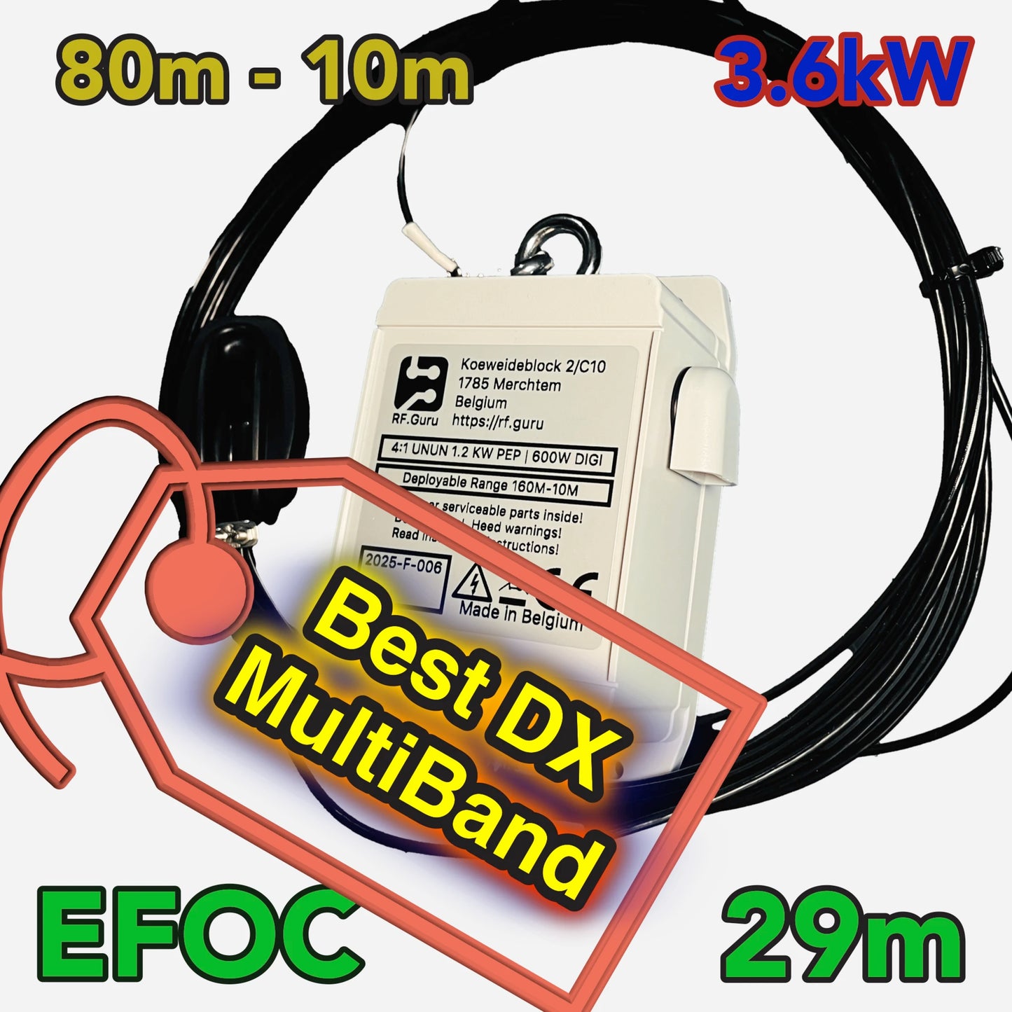
3.6kW End-fed Off-Center EFOC29 80-10M
3.6kW End-fed Off-Center EFOC29 80-10M
Couldn't load pickup availability
EFOC29: A Defined Radiator and a Controlled Return Path
A 29 m multiband HF radiator with an integrated 4:1 UNUN and two selectable return-path configurations. The wire is deliberately supplied long so the installed antenna can be measured, folded back and tuned before anything is cut.
Each EFOC29 transformer assembly is built and tested by hand. Fulfilment normally takes approximately 2–3 weeks, depending on order volume.
The cutting machine supplies more wire than the 29 m electrical starting dimension. Unroll and measure the delivered stock, then tune with the surplus folded back.
The current path is part of the antenna. In the coax-counterpoise version, approximately the first 12 m of coax exterior is the short return path. The first supplied choke ends that section; the remaining coax belongs on the station side of the boundary.
Choose the Return-Path Configuration
The first choke is installed at approximately 12 m from the feedpoint. The supplied arrangement is a practical baseline for around 200 W SSB or 100 W FT8 in a clean installation.
The return wire connects to the stainless-steel M6 terminal. This option does not include the 26 m coax or the two large ferrite chokes.
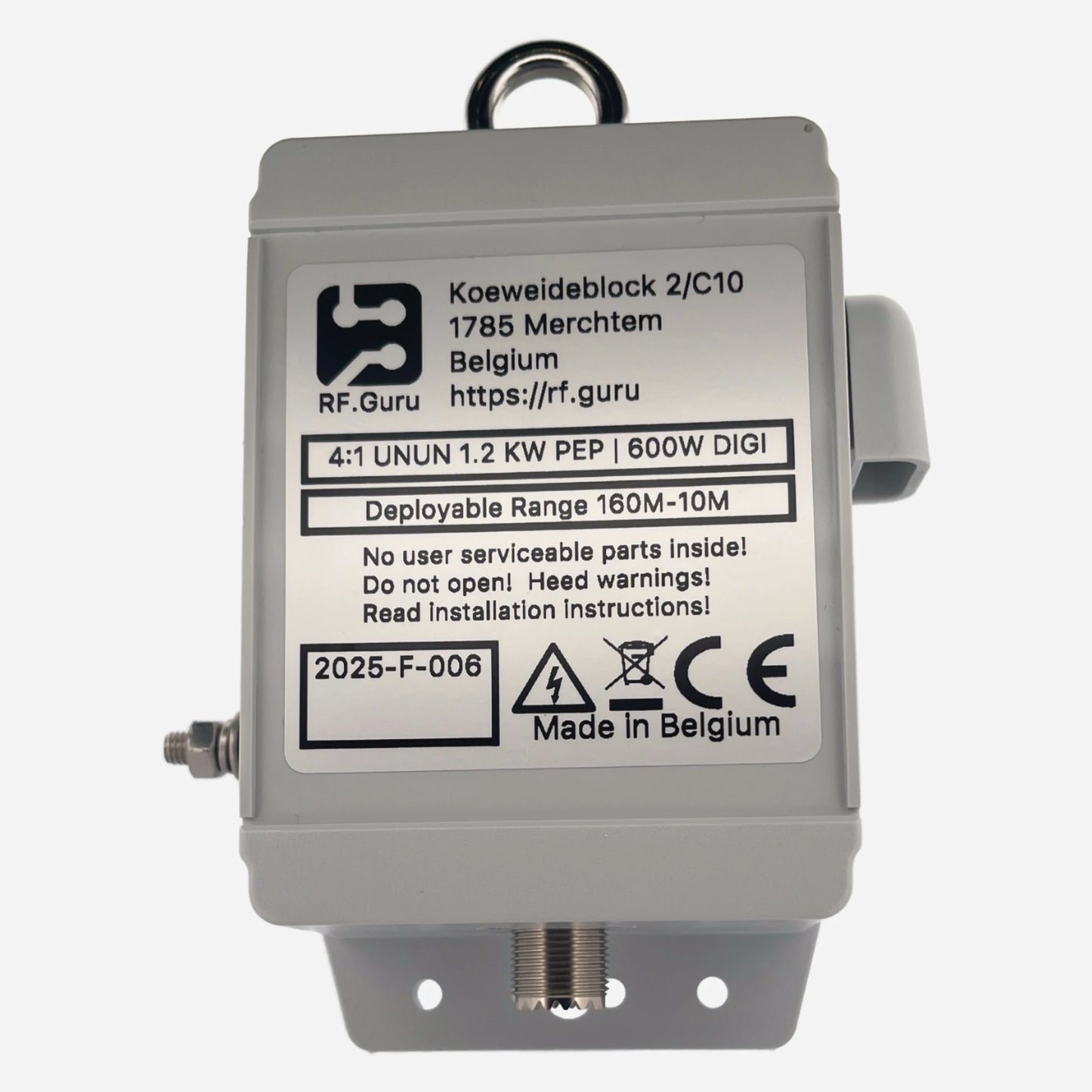
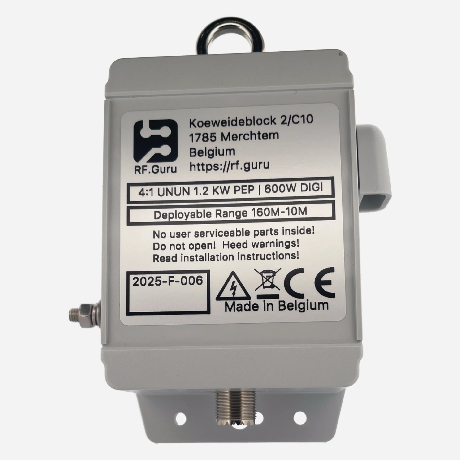
The transformer interfaces the installed EFOC impedance with a nominal 50 Ω feed system. Final impedance still depends on geometry, height, ground and surroundings.
Band and Installation Boundary
| Item | Current specification |
|---|---|
| Radiator | 29 m electrical starting dimension; physical stock is intentionally supplied longer for measurement and fold-back tuning |
| Near-resonant bands | 80 m, 40 m, 20 m, 17 m, 12 m and 10 m |
| Tuner use | 60 m requires an external tuner; 30 m and 15 m may require one depending on installation |
| High bands | On 15 m, 12 m and 10 m the long wire can form multiple lobes and nulls; orientation and geometry matter |
| Transformer | Integrated 4:1 UNUN; published insertion loss below 0.2 dB within the qualified product boundary |
| Typical installed VSWR | Below 2.5:1 on supported bands with a suitable installation; not a universal guarantee |
| Connector and enclosure | SO-239; connector weatherproof to IP66 when correctly sealed; UV-resistant polycarbonate enclosure rated IP64 |
| Approximate weight | 650 g |
Power Versions
| Version | ICAS | CCS | FT8/FT4 |
|---|---|---|---|
| Single core | 2,400 W PEP at VSWR < 2.0:1 | 1,200 W PEP at VSWR < 2.0:1 | 850 W at VSWR < 1.5:1 |
| Dual core | 3,600 W PEP at VSWR < 2.0:1 | 1,800 W PEP at VSWR < 2.0:1 | 1,250 W at VSWR < 1.5:1 |
Ratings belong to the declared conditions. Waveform, duty cycle, mismatch, cooling, connector state, feedline, choke and common-mode current all matter. The complete antenna is limited by its weakest component.
Construction
Hard-drawn, tinned copper with a durable XLPE sheath, supplied long for final measurement and tuning.
Integrated 4:1 impedance transformer using PTFE-insulated winding wire and ferrite selected for stable HF operation.
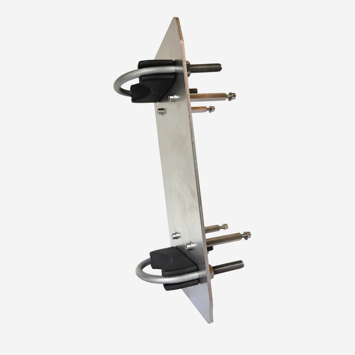
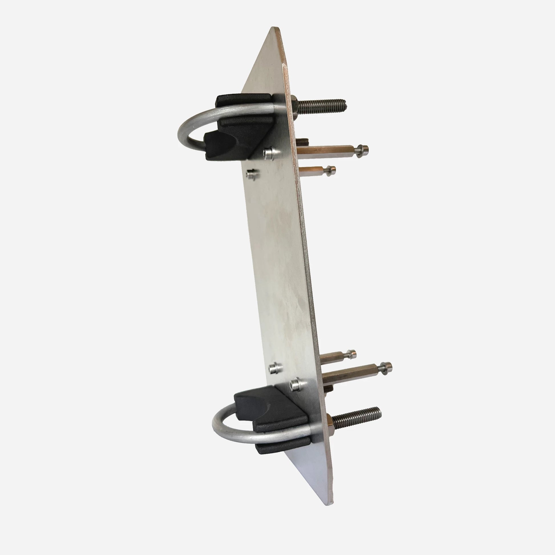
UV- and impact-resistant enclosure with professional SO-239 connection and stainless mounting provision.
Installation Manuals
Wire measurement, layout choices, the 12 m return section, two choke boundaries, tuning and safety.
De volledige Nederlandstalige installatie- en afstemprocedure.
Choose and verify the common-mode boundary for the actual installation and power.
Select the Small 120 × 91 × 62 mm kit for rigid mast mounting.
Follow the Current Path, Not Just the SWR
Explore more RF.Guru technical articles on end-fed systems, return paths, chokes and antenna measurement—and subscribe for new engineering notes.
Join the notification list →Mini-FAQ
- Is the delivered wire exactly 29 m? No. Extra wire is supplied intentionally; measure and mark the 29 m starting dimension before folding or cutting.
- Where does the first coax-version choke go? At approximately 12 m from the feedpoint, ending the intended exterior-coax return section.
- Does every version include coax and chokes? No. The M6-terminal version uses a separate 13 m counterpoise and does not include the coax/choke package.
- Which bands may need a tuner? 60 m requires one; 30 m and 15 m may require one depending on the installation.
- Do the transformer ratings automatically apply to the supplied choke? No. Every component must be qualified for its own current, voltage, frequency, duty and thermal conditions.
Share